ncgoblin's Build Thread - 2005 SS/SC North Carolina
- Thread starter ncgoblin
- Start date
ncgoblin
Goblin Guru
So I read online that if your boost gauge read boost when hitting the throttle in neutral it could be a faulty MAP sensor this is my case.If you want to be cost conscious i would start with the MAP sensor.
ctuinstra
Goblin Guru
On the SS/SC, there are two MAP sensors. One is ambient (for reference) and the other is in the intake. The problem is both connectors are the exact same. Make sure to have them plugged into the correct sensor. If I was at home, I could get you the wire color for each. That is about the only way to tell the difference.
ncgoblin
Goblin Guru
Please take a photo if you are able I have off today so I’m replacing the charger intake MAP sensor that had a crack in the housing it may work but it’s better to be safe. The MAF sensors that both use the same plug may or may not be plugged up correct. I do know when I unplug the MAF in the intake the car isles terribly.On the SS/SC, there are two MAP sensors. One is ambient (for reference) and the other is in the intake. The problem is both connectors are the exact same. Make sure to have them plugged into the correct sensor. If I was at home, I could get you the wire color for each. That is about the only way to tell the difference.
Please take a photo when you get a chance
Thanks for your help!
ncgoblin
Goblin Guru
Follow-up the supercharger upper MAP sensor is replaced and she’s hauling! Unfortuntly I have low pressure on my brake line even though I don’t see bubbles I may have a leak inside the trans due to the upper block upper gromet or the line inside which would mean dropping the engine . I am going to rebleed brakes first.
But my hopes are high she’s running!
But my hopes are high she’s running!
Briann1177
Goblin Guru
Glad you got it fixed. I'm curious about your gauges. Not sure why your security light stays on and the display shows --------. I wonder if there is an issue with the low speed green wires. Then again it might be a ground problem too. Seems like 80% of the issues here are ground related.
ncgoblin
Goblin Guru
It may be a ground issue at this point I’m not too worried. Someone suggested grounding the BCM chassis I thought?Glad you got it fixed. I'm curious about your gauges. Not sure why your security light stays on and the display shows --------. I wonder if there is an issue with the low speed green wires. Then again it might be a ground problem too. Seems like 80% of the issues here are ground related.
ctuinstra
Goblin Guru
I can't wrap my head around "leak inside the trans" being a brake issue. I'm not sure what you mean by this.Follow-up the supercharger upper MAP sensor is replaced and she’s hauling! Unfortuntly I have low pressure on my brake line even though I don’t see bubbles I may have a leak inside the trans due to the upper block upper gromet or the line inside which would mean dropping the engine . I am going to rebleed brakes first.
But my hopes are high she’s running!
Glad to see the MAP fixed the issue.
Here are the colors of the wires of the MAP on the supercharger any ways.
ncgoblin
Goblin Guru
Thanks for the connector I’ll double check it. The line in the trans may be leaking but now that I think through the reason my pedal hits the floor it is unrelated they share he same reservoir but not the same hydrolic system. I probably have air somewhere I’ll bleed tonight or tomorrow.I can't wrap my head around "leak inside the trans" being a brake issue. I'm not sure what you mean by this.
Glad to see the MAP fixed the issue.
Here are the colors of the wires of the MAP on the supercharger any ways.
View attachment 6429
Thanks
ctuinstra
Goblin Guru
Oh, you are referring to the clutch. I was thinking automatic transmission. Yes, two completely different systems.Thanks for the connector I’ll double check it. The line in the trans may be leaking but now that I think through the reason my pedal hits the floor it is unrelated they share he same reservoir but not the same hydrolic system. I probably have air somewhere I’ll bleed tonight or tomorrow.
Thanks
ncgoblin
Goblin Guru
Brakes are great! Lonny recommended going the old style pushing brake pedal and popping bleeder this worked! It actually makes sense the bleeder kit I had that pressurizes the system works great for replacing fluid and getting air out of the line but it won’t help with the master cylinder if air is captured.Oh, you are referring to the clutch. I was thinking automatic transmission. Yes, two completely different systems.
I found another problem which I should have saw a long time ago none of my gauges work lol. They all light up but don’t actually function. Any ideas?
I'd venture to guess this is tied to your security light, very peculiar. But i did not experience that.Brakes are great! Lonny recommended going the old style pushing brake pedal and popping bleeder this worked! It actually makes sense the bleeder kit I had that pressurizes the system works great for replacing fluid and getting air out of the line but it won’t help with the master cylinder if air is captured.
I found another problem which I should have saw a long time ago none of my gauges work lol. They all light up but don’t actually function. Any ideas?
ctuinstra
Goblin Guru
You may be missing the Low Speed Data circuit. It's the dark green wire. There was a bunch of them all going to one big black molded connection that the video had you cut out and solder together. Pin 9, I believe. Those lines carry all of the information. And obviously there needs to be a ground to the dash.I found another problem which I should have saw a long time ago none of my gauges work lol. They all light up but don’t actually function. Any ideas?
The illumination is a completely different circuit and 100% isolated from the rest of the dash. I know this because I just reworked ours with LEDs. Those are Pin 16 and 8 of the dash harness (top right and lower right looking from the rear of the dash).
Last edited:
ncgoblin
Goblin Guru
You may be missing the Low Speed Data circuit. It's the dark green wire. There was a bunch of them all going to one big black molded connection that the video had you cut out and solder together. Pin 9, I believe. Those lines carry all of the information. And obviously there needs to be a ground to the dash.
The illumination is a completely different circuit and 100% isolated from the rest of the dash. I know this because I just reworked ours with LEDs. Those are Pin 1 and 8 of the dash harness (top right and lower right looking from the rear of the dash).
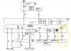
Your are correct pin 9 circuit 5060 is for the low speed data circuit of the instrument panel plug. It looks like it routes back to the BCM-C1 plug. What's odd is (2) PINs for that circuit 5060 pin 18, and 36 (shown below) are depicted on the BCM-C1 plug.You may be missing the Low Speed Data circuit. It's the dark green wire. There was a bunch of them all going to one big black molded connection that the video had you cut out and solder together. Pin 9, I believe. Those lines carry all of the information. And obviously there needs to be a ground to the dash.
The illumination is a completely different circuit and 100% isolated from the rest of the dash. I know this because I just reworked ours with LEDs. Those are Pin 1 and 8 of the dash harness (top right and lower right looking from the rear of the dash).
From OBD I receive continuity from Pin 8 (facing towards connector right/left), and Pin 14 of the instrument panel connector.
I believe the next logical step is to test from pin 9 of the instrument panel plug to the BCM-C1 pins 18, and 36 to see which one has continuity.
I believe
Attachments
-
 155.6 KB Views: 261
ctuinstra
Goblin Guru
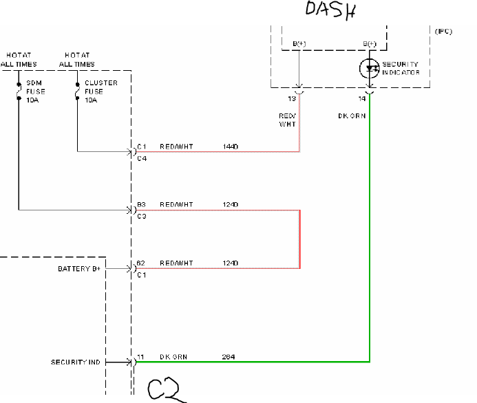
I think you have one too many green wires tied together. I'm going to keep looking but pin 14 (D-GN) Security Indicator Supply Voltage should not be connected to the GM Low Speed Data.
Pin 14 of the instrument cluster should ONLY go directly to C2 Pin 11 of the BCM. If it is showing continuity to the GM LAN wires, cut it out of that circuit.
Pin 14 of the instrument cluster should ONLY go directly to C2 Pin 11 of the BCM. If it is showing continuity to the GM LAN wires, cut it out of that circuit.
ctuinstra
Goblin Guru
Pin C1 36 is abandon. It went to the Vehicle Communication Module that was removed. This is part of the OnStar system.I believe the next logical step is to test from pin 9 of the instrument panel plug to the BCM-C1 pins 18, and 36 to see which one has continuity.
Pin 9 of the Instrument Cluster should have continuity to BCM Pin C2 38 (according to my wiring diagram).
ncgoblin
Goblin Guru
You sir know your wiring between my research, your instruction, and continuity testing I was able to cut one of the green wires out of the OBD plug, wire from pin 9 to C2 38. Pin 14 to C2 11 I also made sure was soldered in. Now we’re in business all gauges work including gas gauge and the security key icon is now gone. While I had the instrument panel partially off I went ahead and followed your guide and razer blade all circuits for faulty lights now the instrument panel looks stock. I have to make some adjuments to the rear taillights and install seat belts then I am ready for state inspection!
Thanks for your help your a huge value to the community.
Thanks for your help your a huge value to the community.