BAR-AIR's build up in Buffalo N.Y.

BAR-AIR

Well-Known Member
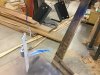
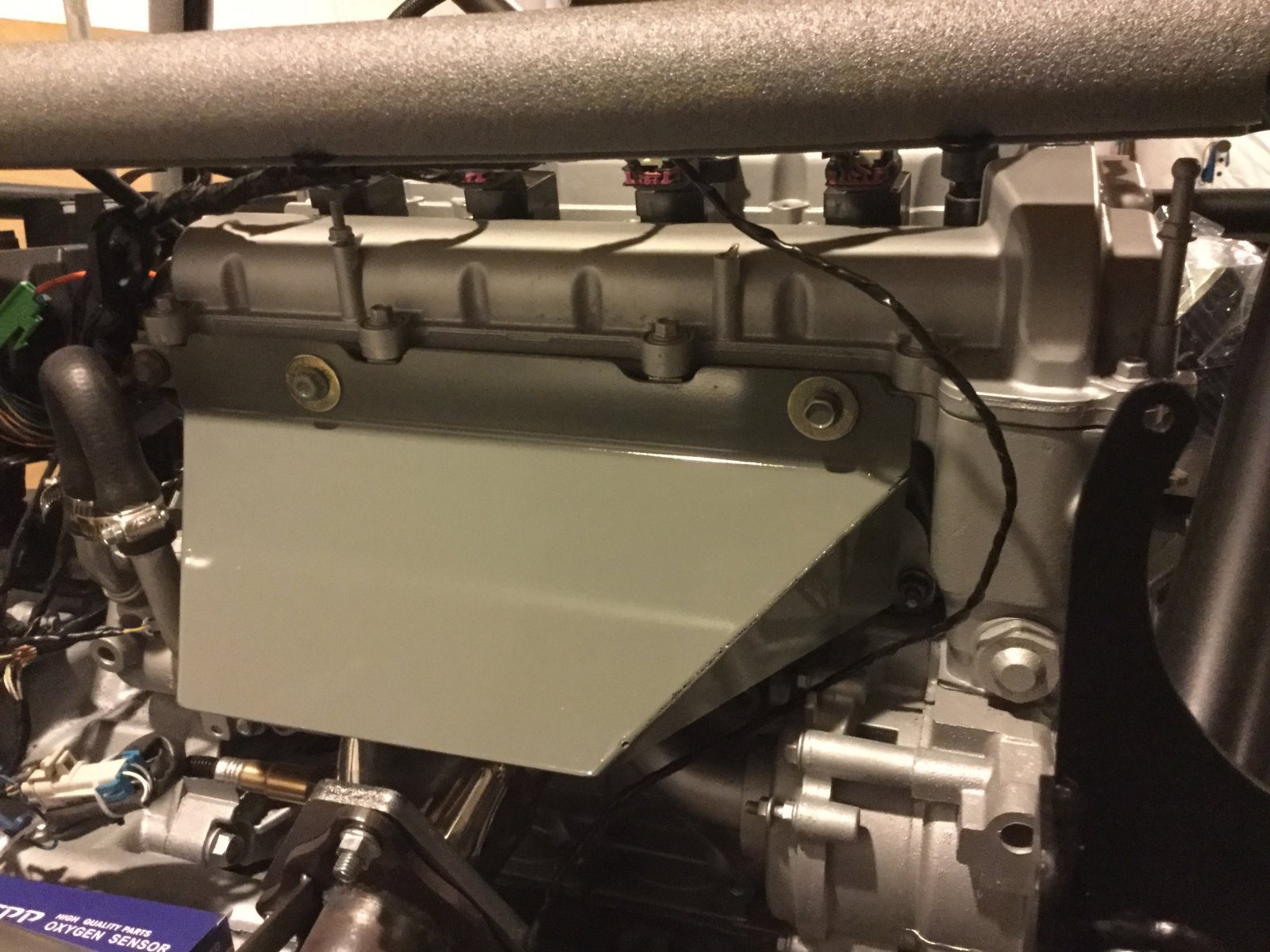
Here is the new heat shield for after market headers....
IMG_1164.JPG

IMG_1165.JPG

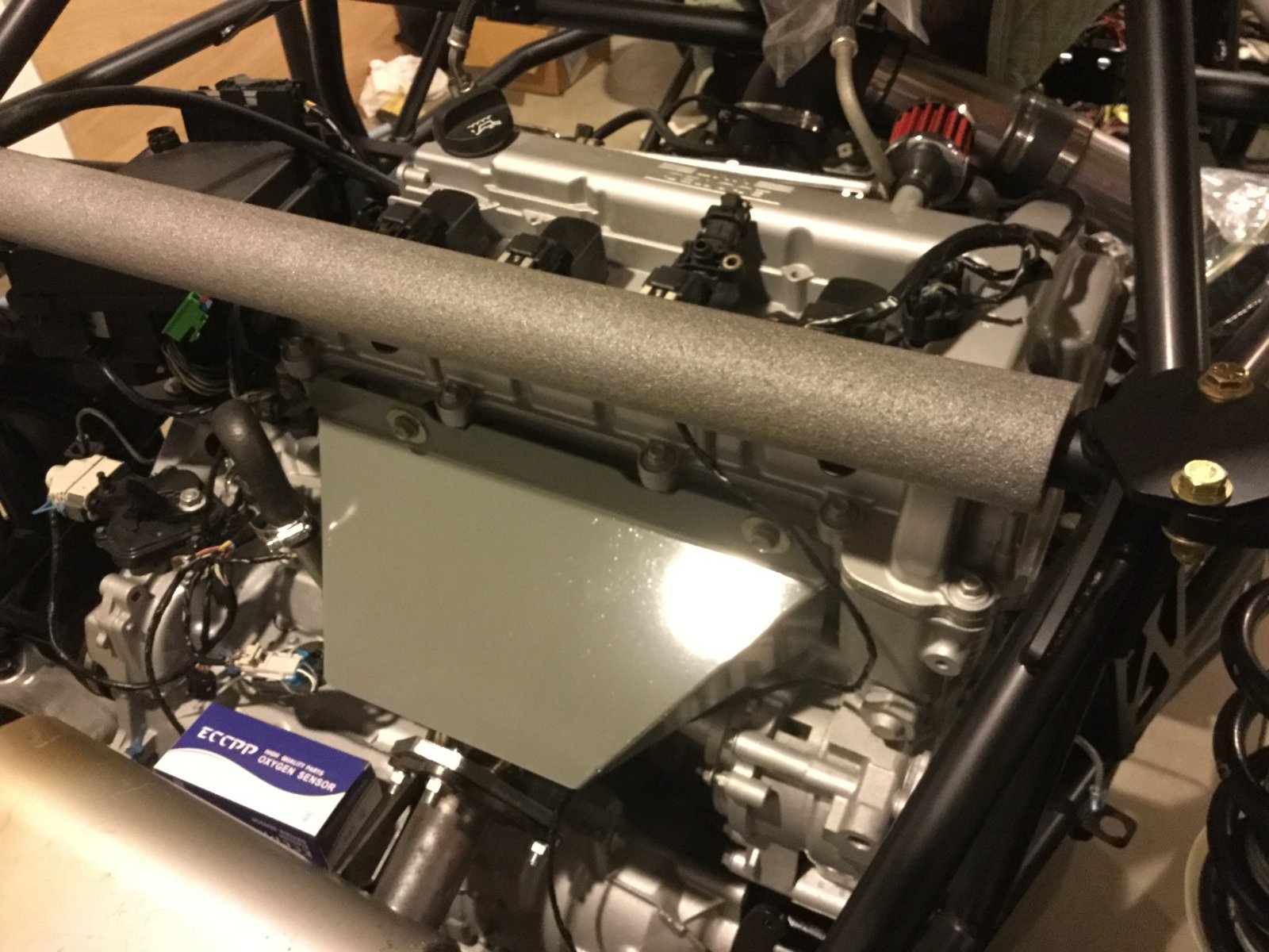
Here is the beginning of the welded new emergency brake mount it is a one sided mount (with the brake handle offset to the drivers side) so that you can still get inside to adjust the cables. The 1" circular hole is for one of the 12v power supplies. There will be a bent cover plate to finish the passengers side.
IMG_1166.JPG
 

BAR-AIR

Well-Known Member
Here is my mock up for the heat shield. If you have access to a finger brake you can bend one up out of a single sheet. I wasn't able to so I welded up the sides.
IMG_1167.JPG

Just a quick note the mounting holes are not parallel the drivers side is lower. I also just took a grinder to get the upper contours (optional)
IMG_1168.JPG

This is one of the blanks before finishing.
 

BAR-AIR

Well-Known Member
Well here is the emergency brake mount using a lokar emergency brake handle. The top of the mount is 2" above the standard channel so there shouldn't be any interference with anything in the channel.
IMG_1170.JPG
Just put a couple riv nut in the top so that I can install the passengers side cover plate (just a piece of thin steel bent to finish the passengers side and top so there will only be a small slot for the handle to stick though.)
IMG_1172.JPG
 

BAR-AIR

Well-Known Member
Well got home today figured I would knock out the emergency brake handle. (One more thing checked off the list).
IMG_1177.JPG

Well not so fast....
Mocked it up in Nate's frame so I knew there are some differences, as in the original frames cross members go right through the channel (different sizes - didn't catch that or that the original channels also have flanges on the top @&$!"? FU.... ).
So either cut the upper flange off or start again....
IMG_1178.JPG

Nate did thank me for finishing his parts first....☠
 

BAR-AIR

Well-Known Member
53231725113__920B6BB2-F916-4CDC-8457-48914110C5B3.JPG
Finally got the emergency brakes in and working on car #10 "BLUE". Ended up cutting the center channel cover into 3 pieces (1 was removed for brake, 2nd is the section with the shifter, 3rd is the front section -you can see the split in front of shifter). The front section is probably going to be replaced with a raised console? With the rear wall in the car it was near impossible to get the center cover off. That may be just an issue with the real early frames (different center channels). But going to cut Nate's cover also just for ease of access.
Relocating the supercooler up an additional 2" to allow new air ducting between the cooler and the new heat shield for the headers (that should give me about 7" of room for air flow) while not optimum should help with reducing the heat from the header transferring to the cooler.
Next week hopefully finish re-plumbing cooler, and start trimming and re contouring hood to meet up with windshield frame so that the wipers will work and try to seal that area.
 

JSATX

Goblin Guru
I’m chopping my center cover as well. Going to tack weld #8 nuts to the inside channel and run pan head short bolts for the cover.
 

BAR-AIR

Well-Known Member
Finally got the rear wing mounts back. Went up to 1/8" on the thickness and added the bottom extension for an additional tube running across the back of the frame didn't want to mount it solid so using expandable soft plugs inside the 1 1/4" tube.
IMG_1221.JPG

IMG_1223.JPG

Initial bolt up on the frame.
IMG_1226.JPG

With the cooler and the rear wing installed. (I have heard that there has been some cracking of the wing? Has anyone done anything different with the top mounts -reason I'm asking is the distance between the outer edge of the upper mounts (attached to the plastic wing) is 25 1/2" where as the distance between the inner edge of the wing mounts is 26 3/4" that means you have to draw in the wing mounts 1 1/4"). The flex is visibly noticeable when standing behind the car.
 

BAR-AIR

Well-Known Member
Here is a photo of the rear wing with some temporary 1/2" spacers mounted into the top of the wing mount. It would need about another 1/8" per side to get the wing mounts actually vertical. (Center rod not installed)... am I missing something is there supposed to be a fabricated angle to use instead of the stock attachments that come with the wing?
IMG_1227.JPG
The outer most attachment screw is at 26 1/4" and the actual distance between the two wing mounts is 26 3/4"!!! So possibly a piece of steel bent to 90 degrees catching all four of the upper wing screws and connecting to the outside of the verticals (don't think I'm going to have enough clearance for the outer screws). Also need a new center rod.
IMG_1228.JPG
 

BAR-AIR

Well-Known Member
Simple 2”x 2” x 1/8” aluminum angle cut down to 1 3/8” on one side then drilled to fit pushed the upper wing mounts to almost the same dimension as the bottom mount.
9CA47801-17B5-4EB6-B2CF-BBA5C7580A84.jpeg
While I was cutting the angle made up a better license plate bracket w/ light. Hopefully getting close to having the back of the car finished up for inspection.
1156A762-E7AA-4BD9-ABF1-B56F706EAFD3.jpeg
 

Attachments

BAR-AIR

Well-Known Member
Nothing to do with build but just finished installing a NSS-8XLTC four post lift in the garage. Still can lift it another 8-10” before hitting the ceiling. As it sits right now I have 6’ of clearance under the runways which works for me (5’-10”).
8C2913E0-CD4E-4C86-AEED-6DD36E6494FC.jpeg

Makes a lot more room in the garage even with the tractor and box blade connected.
74EE8A1C-22CE-4448-91AB-4639CFCC06A2.jpeg
 

ctuinstra

Goblin Guru
That's cool! I always wanted one of those. I have a JD tractor muck like that and a corvette in the shop and I'm quickly running out of room.
 

BAR-AIR

Well-Known Member
Thanks,
My wife and I have been very fortunate. Up to this house we had always bought junk and brought it back to life. We ended up building this one a couple of years ago still not completely finished (still need to make the upper cabinets for the kitchen). But this is Nate’s Goblin in the basement and my actual shop behind the canvas tarp.
D7A7F791-D4F2-428D-985D-B03B1C6882AF.jpeg
 

BAR-AIR

Well-Known Member
Evening Guys....
Was just working with Nate on his car had a question on the fuel pump wiring.
43BC647A-BC4A-4455-A799-3D068E6F9EB1.jpeg

California emissions so here are the initial wires.
AF0BBDFE-4C53-4118-86F6-13CAD6D233E7.jpeg

New style fuel pump to be used on the Goblin.
2F026723-0A01-4DA7-8EE6-80BAA6BFE138.jpeg

When I did my car I forgot to note the actual wiring. If someone could just check my work. Would hate to smoke a new pump.
 

Briann1177

Goblin Guru
According to my '09 service manual, your diagram is correct. However, for some reason the wires on my connector are in a different order.

Fuel_Pump (1).jpg
 
Last edited:

BAR-AIR

Well-Known Member
Is that an OEM plug or generic. I bought two generic plugs and both have different wire color sequences. But I think my orientation for the wire placement is right.
 
Top