ctuinstra's City Goblin - 07 SS/SC donor 2.0
- Thread starter ctuinstra
- Start date
ctuinstra
Goblin Guru
I used a special paint from Eastwood specifically for radiators. The coating is extremely thin so as not to affect the cooling. It's much thinner than normal enamel. I lightly sanded the aluminum and the sanding marks are almost visible, and this was using something like 220 grit. One can will do both sides. I put 4-5 coats on it all all different angles.I couldnt find it noted in your posts.... did you powder coat the radiator or spray paint? Been thinking about spray painting mine but wondering if it will have any adverse affects on cooling...
https://www.eastwood.com/ew-radiator-black-12oz-satin-finish.html
ctuinstra
Goblin Guru
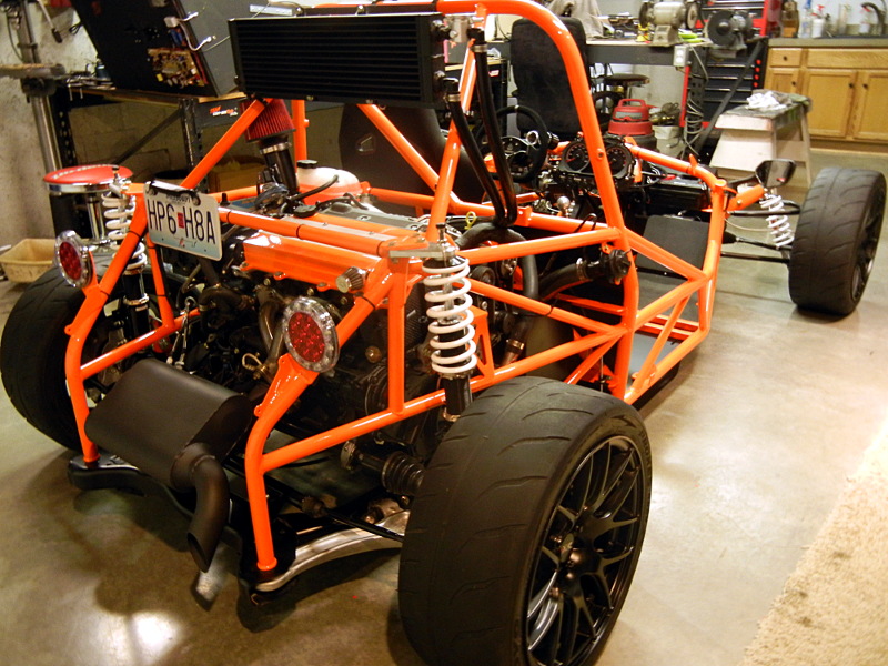
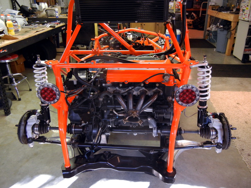
Got a few more things dones yesterday and today. We hooked up all of the brake lines and coolant lines. Repaired some wiring in the front; I'm really surprised I didn't have a lot more of a mess with the wiring, hope I'm not jinxing myself. Mounted all of the suspension components. We did find the rear solid engine mount was in fact bent. I figured it had to be. The engine and the subframe weren't lining up with the frame so we removed the rear solid engine mount and it lined up much better. Thankfully Adam had shipped me a replacement.
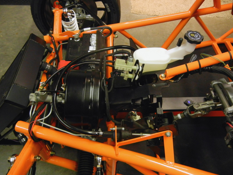
We will be adding fluids, coolant, oil, and brake fluid. Burp the system and bleed the brakes. Still have some more wiring to sort out in the front but it's not too bad. There is a locking connector on the BCM that took damage to the locking mechanism. I'm going to try it without the lock and hope for the best. I'm still debating on trying to find another connector and de-pinning it and moving them over to a replacement. Could be quite a task and I don't want to mess it up.
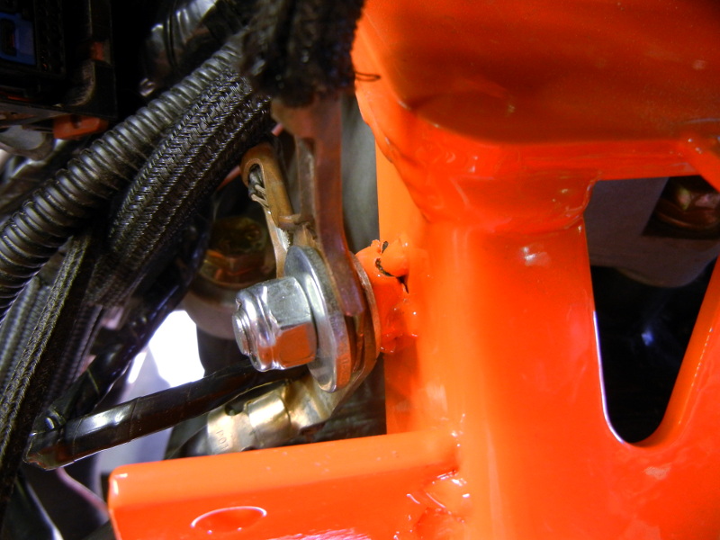
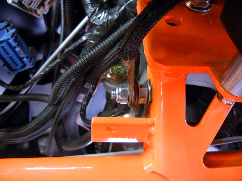
I am really loving the welded on ground lug on the driver side engine mount. We didn't have one on the first frame. I had everything bolted up like I wanted it and was tightening it down and then SNAP! Broke the welds on the bolt. I ended up drilling a hole and clearing away the powder coating, then running a longer bolt through the hole. I locked it down with a star washer and nut and then bolted on the ground lugs. Love this setup much more than what we had on the first frame.
We will be adding fluids, coolant, oil, and brake fluid. Burp the system and bleed the brakes. Still have some more wiring to sort out in the front but it's not too bad. There is a locking connector on the BCM that took damage to the locking mechanism. I'm going to try it without the lock and hope for the best. I'm still debating on trying to find another connector and de-pinning it and moving them over to a replacement. Could be quite a task and I don't want to mess it up.
I am really loving the welded on ground lug on the driver side engine mount. We didn't have one on the first frame. I had everything bolted up like I wanted it and was tightening it down and then SNAP! Broke the welds on the bolt. I ended up drilling a hole and clearing away the powder coating, then running a longer bolt through the hole. I locked it down with a star washer and nut and then bolted on the ground lugs. Love this setup much more than what we had on the first frame.
ctuinstra
Goblin Guru
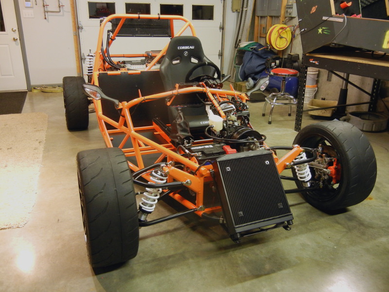
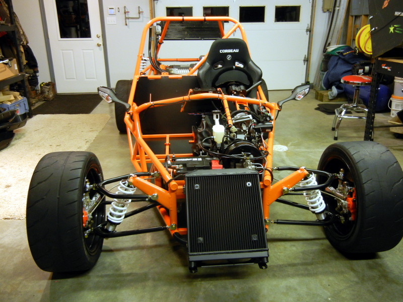
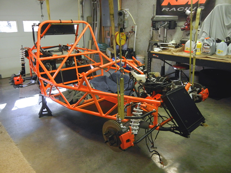
Here is our progress so far. We are going to work on it some more this weekend. I'm not sure yet if I'm going to push it point of trying to start it or not. We'll see how it goes. We are very close.
Once we get it started and it seems to be going well, I'm going to remove the key cylinder and change it over to a push-to-start system. I can't tell you how many times I buckled up only to find out the keys are still in my pocket. My daily driver is a push to start and I come to love it. Still undecided on the key fob type or the proxy card.
Once we get it started and it seems to be going well, I'm going to remove the key cylinder and change it over to a push-to-start system. I can't tell you how many times I buckled up only to find out the keys are still in my pocket. My daily driver is a push to start and I come to love it. Still undecided on the key fob type or the proxy card.
Brian74
Goblin Guru
I’m big on all of this stuff to. I have a whole laundry list of various tabs I need to weld. Despite being subtle it really improves the overall finish.Before the frame was powder coated, I welded this tab on for the fuse box instead of using the clamp and piece of angle iron. I really like the little things like this. Not everything is perfect, but you know how it is, sometimes it the little details.
View attachment 6306
ctuinstra
Goblin Guru
I worked on the LEDs in the dash today. We are about to the point of hooking up the electrical in order to start it for the first time again. Changing the illumination from bulbs to LEDs is a lot harder than I was hoping. The bulbs are 12V bulbs and all of them are wired in parallel. LEDs just don't work as well that way. I needed to add a current limiting resistor inline with each LED, and with six LEDs, that would be a lot of resistors to wire up. I ended up running three pair of LEDs. Each pair had its own resistor. My first calculation of the limiting resistor gave the correct current of right around 60mA (they are rated at 65mA continuous) but the resistor, even though its a 2W, was still getting too warm for my liking. I tried dropping the current with a larger value resistor and while it helped, it was still getting too warm long term. I finally settled on using a voltage regulator to drop the voltage down to a more manageable level of 5V and then used the current limiting resistor. This is working very well but I'm still experimenting with the VR output. Six or eight volt regulator would increase the current some over the LEDs and would lower the amount of voltage it would have to drop (keeping the VR happy).
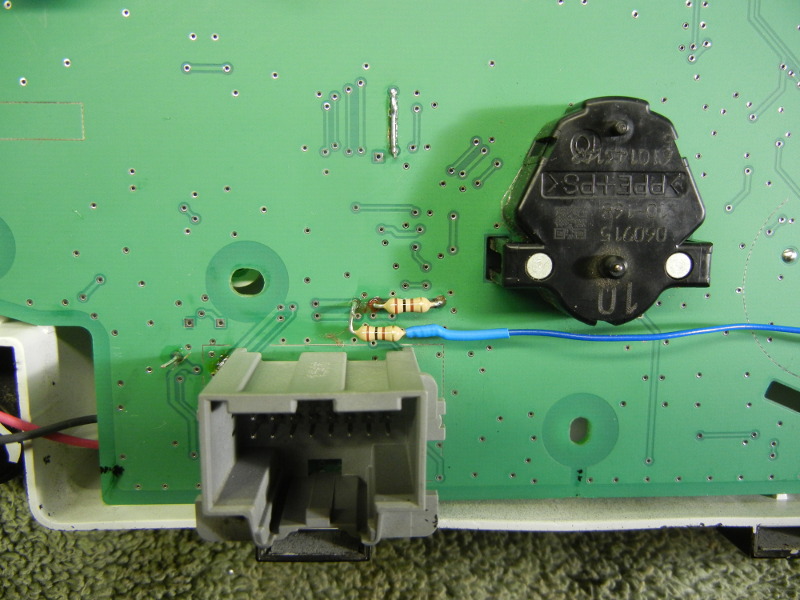
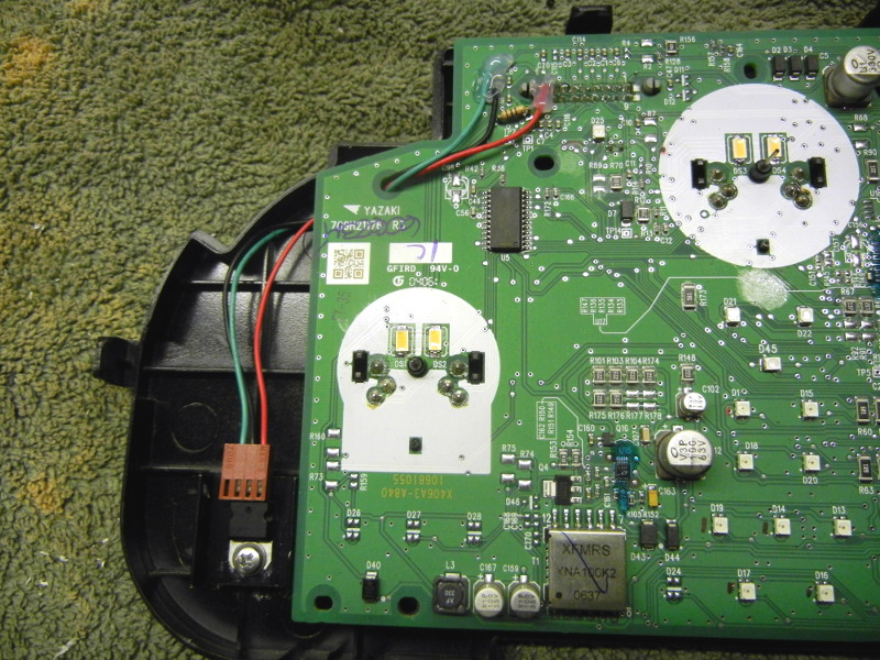
I used through board jumpers as a good place to mount the resistors. I drilled out the holes with a #72 (.0250") orifice bit, cut the traces and mounted the resistors between them. I couldn't always do it and did have to jumper-wire one of them.
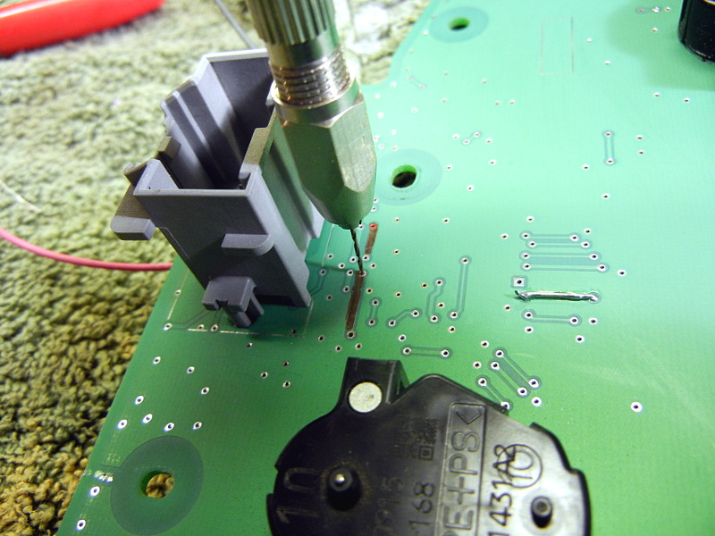
Here you see one of the resistors. This one is for the left gauge. The red and black wires are only temporary as I used them to power the circuit for testing. The resistor you see are not the 2W since I'm using a VR now. Since they have such a small amount of power to dissipate, I could go back to the 1/4W.
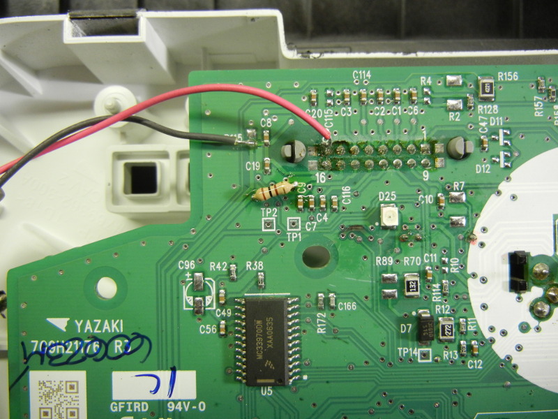
Here are the other two resistors for the gas gauge and the right gauge. I had to break the circuit here and jumper the resistor all the way over the the right gauge.
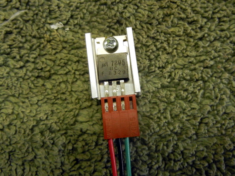
This is the voltage regulator mounted on a heat sink. Without the heat sink, it doesn't even warm up, but I wanted to be on the safe side. It will be wired into the board with the wires and mounted to the case. It has a plug on it to unplug it to open up the dash. I could have tried to solder it directly to the board but the chances of coming up with a good mounting spot with the required connections close enough was going to be impossible.
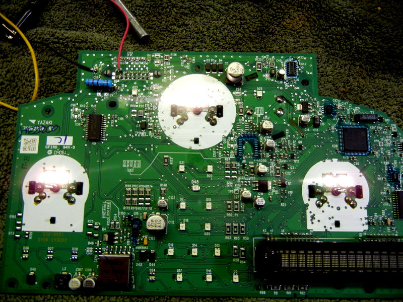
Bench testing.

All six lit up and working on the bench. (photo was taken before I changed out the resistor). These are currently being driven at 30mA per pair so that's about 15mA per LED, much lower than the nominal. However by changing the VR value and possibly the resistor values, I hope to increase that to around 45-50mA per pair. I just don't want it running warm. Even with this low of current, it's still much brighter than the original and the color temp is a lot better.
This is not a job for the D.Y.I. type. I was hoping I could make this fairly easy so anyone could do it, but I'm not the electrical engineer. I'm not sure how you could drive six LEDs at 60mA each all wired in parallel (correctly and safely). If you know of a good way, let me know and maybe we can some up with something for everyone. I did think about running a couple of them in series, and that would have been the best, but the PWB does not let you do that easily by any means. You would have to hard wire each and everyone of them.
I used through board jumpers as a good place to mount the resistors. I drilled out the holes with a #72 (.0250") orifice bit, cut the traces and mounted the resistors between them. I couldn't always do it and did have to jumper-wire one of them.
Here you see one of the resistors. This one is for the left gauge. The red and black wires are only temporary as I used them to power the circuit for testing. The resistor you see are not the 2W since I'm using a VR now. Since they have such a small amount of power to dissipate, I could go back to the 1/4W.
Here are the other two resistors for the gas gauge and the right gauge. I had to break the circuit here and jumper the resistor all the way over the the right gauge.
This is the voltage regulator mounted on a heat sink. Without the heat sink, it doesn't even warm up, but I wanted to be on the safe side. It will be wired into the board with the wires and mounted to the case. It has a plug on it to unplug it to open up the dash. I could have tried to solder it directly to the board but the chances of coming up with a good mounting spot with the required connections close enough was going to be impossible.
Bench testing.
All six lit up and working on the bench. (photo was taken before I changed out the resistor). These are currently being driven at 30mA per pair so that's about 15mA per LED, much lower than the nominal. However by changing the VR value and possibly the resistor values, I hope to increase that to around 45-50mA per pair. I just don't want it running warm. Even with this low of current, it's still much brighter than the original and the color temp is a lot better.
This is not a job for the D.Y.I. type. I was hoping I could make this fairly easy so anyone could do it, but I'm not the electrical engineer. I'm not sure how you could drive six LEDs at 60mA each all wired in parallel (correctly and safely). If you know of a good way, let me know and maybe we can some up with something for everyone. I did think about running a couple of them in series, and that would have been the best, but the PWB does not let you do that easily by any means. You would have to hard wire each and everyone of them.
Briann1177
Goblin Guru
If all the LEDs are the same with the same forward voltage and current, I'm pretty sure you'd need six resistors that have the same value of whatever value you'd need for one LED. Essentially 360 mA divided evenly across six branches.
Did you figure about 175 Ohms? They need to be 1W resistors if you're using 12V. 1/4W at 5V.
Did you figure about 175 Ohms? They need to be 1W resistors if you're using 12V. 1/4W at 5V.
Last edited:
ctuinstra
Goblin Guru
I started out with 82 Ohms for two LEDs (forward voltage of 2.9, not 1.2) in parallel to get about 60mA each (Vf=2.9, Vt=12, Vr=9.1, It=.111mA (55mA each)). The power the resistor would have to dissipate would be 1W (9.1*.111), so I used a 2W and it might have handled it but it was generating too much heat for me. I tried up to 180 Ohms and even though this drastically cut the current, it still created too much heat, just not as much. If I could have wired three in series, that would have worked the best with one small current limiting resistor.If all the LEDs are the same with the same forward voltage and current, I'm pretty sure you'd need six resistors that have the same value of whatever value you'd need for one LED. Essentially 360 mA divided evenly across six branches.
Did you figure about 175 Ohms? They need to be 1W resistors.
Last edited:
IDRVSLO
Goblin Guru
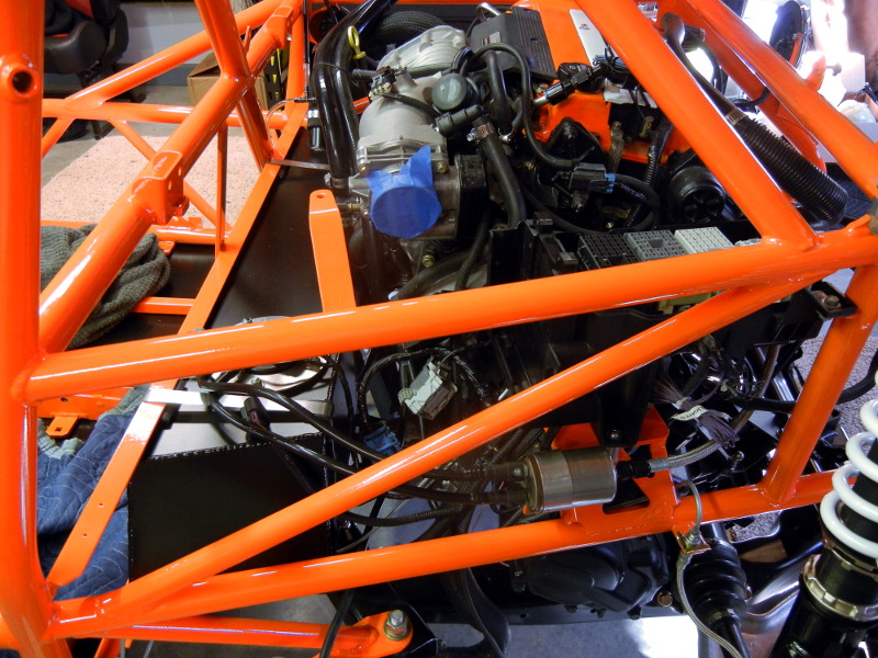
I used the same mounts that Chad used. A few close ups in my thread.Chad - would you be able to provide close up pics (or details) on how you mounted your SC intercooler? I just received all my parts from ZZP and plan to get it all installed this weekend if i dont run into misc issues.
ctuinstra
Goblin Guru
Here is a link to the first build that shows some good pictures.Chad - would you be able to provide close up pics (or details) on how you mounted your SC intercooler? I just received all my parts from ZZP and plan to get it all installed this weekend if i dont run into misc issues.
http://dfkitcar.com/forum/index.php?threads/ctuinstras-city-goblin-07-ss-sc-donor-licensed.338/page-10
Last edited:
Here is a link to the first build that shows som good pictures.
http://dfkitcar.com/forum/index.php?threads/ctuinstras-city-goblin-07-ss-sc-donor-licensed.338/page-10
Thanks, that helps. Where did you get the 1 1/4 inch clamps?
ctuinstra
Goblin Guru
This link should tell you everything you need to know. Scroll down about halfway
http://dfkitcar.com/forum/index.php?threads/ctuinstras-city-goblin-07-ss-sc-donor-licensed.338/page-11
http://dfkitcar.com/forum/index.php?threads/ctuinstras-city-goblin-07-ss-sc-donor-licensed.338/page-11
ctuinstra
Goblin Guru
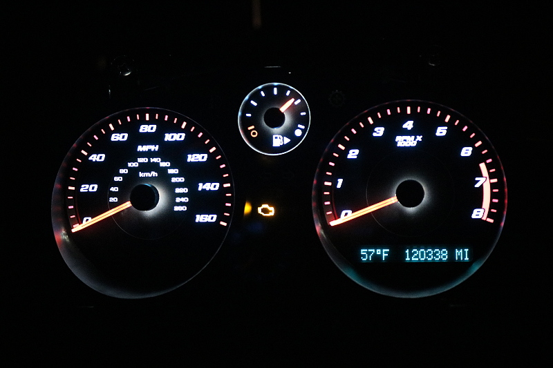
Dash LED conversion is complete! I was hoping this would be much easier and there could be thread on how to do it yourself, but in the end, it's much too difficult to do it the way I did it to guide others through it. Not that it can't be done, I just don't want the stress of someone trying to follow me and it turns out to be a disaster. I'll feel too guilty.
The biggest issue is dropping the 12V-14V down to the 2.9 and limiting the current across each LED to less than 60mA. Simple current limiting resistors have to dissipate too much power and get warm. It would be very easy if they could have been wired in series instead of parallel and therefore the drop would have been down to, for example, 8.7 (3 x 2.9) across all of the LEDs and the resistor would have had to dissipate only 3.3V (12 - 8.7). That would have been very easy. But chopping up the traces and re-wiring each just would have been chaos.
So I ended up finding that a 8V regulator to help drop the overall incoming 12V and then letting the individual resistors drop the rest kept the resistors cool and without heating up the regulator. I put the regulator on a heat sink and mounted it to about the only spot inside that it would fit. With the connector on the regulator, this allows for everything to be removed and opened up easily in the future.
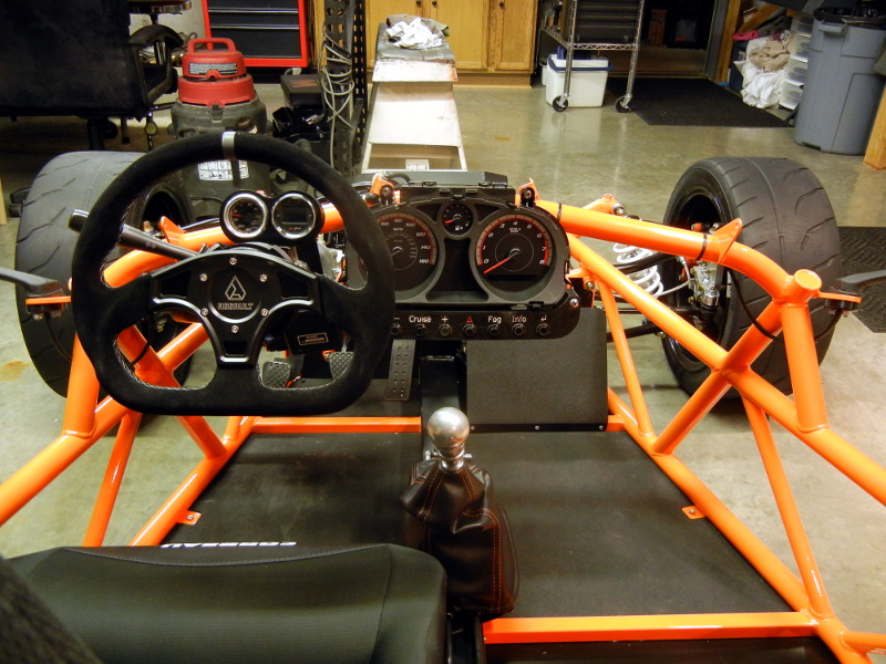
It's very hard to get a good picture of the dash. Even with my daughter's good camera (and a poor operator), I just couldn't hold still long enough to keep it from blurring. This is actually powered by the ignition and not the test bench. Yes, I have the battery connected to the car now.
The glow in the center of the dials is because I don't have them pressed on all the way. I wanted to check and reset their position before I button it back up once and for all. My MIL is on because I haven't started the engine. I re-connected the MIL and have since disabled all of the codes using HP tuners that no longer apply. I like the very clean dash. It bugged me to no end to see any type of warning or indicators on all the time. I even have the coolant level fixed now by replacing the coolant tank. Also the BRAKE indicator is gone.
Our donor had 116K on it when we stripped it. Somewhere I have a photo of it. That boy drove the hell out of the car during those couple of months. That's a lot of groceries!
The biggest issue is dropping the 12V-14V down to the 2.9 and limiting the current across each LED to less than 60mA. Simple current limiting resistors have to dissipate too much power and get warm. It would be very easy if they could have been wired in series instead of parallel and therefore the drop would have been down to, for example, 8.7 (3 x 2.9) across all of the LEDs and the resistor would have had to dissipate only 3.3V (12 - 8.7). That would have been very easy. But chopping up the traces and re-wiring each just would have been chaos.
So I ended up finding that a 8V regulator to help drop the overall incoming 12V and then letting the individual resistors drop the rest kept the resistors cool and without heating up the regulator. I put the regulator on a heat sink and mounted it to about the only spot inside that it would fit. With the connector on the regulator, this allows for everything to be removed and opened up easily in the future.
It's very hard to get a good picture of the dash. Even with my daughter's good camera (and a poor operator), I just couldn't hold still long enough to keep it from blurring. This is actually powered by the ignition and not the test bench. Yes, I have the battery connected to the car now.
The glow in the center of the dials is because I don't have them pressed on all the way. I wanted to check and reset their position before I button it back up once and for all. My MIL is on because I haven't started the engine. I re-connected the MIL and have since disabled all of the codes using HP tuners that no longer apply. I like the very clean dash. It bugged me to no end to see any type of warning or indicators on all the time. I even have the coolant level fixed now by replacing the coolant tank. Also the BRAKE indicator is gone.
Our donor had 116K on it when we stripped it. Somewhere I have a photo of it. That boy drove the hell out of the car during those couple of months. That's a lot of groceries!
ctuinstra
Goblin Guru
Kaleb is home for winter break. We worked on the car today and got a few things finished. We are getting really close to putting it on the ground and running around with it again.
Today we mounted the rear solid engine mount, tunnel cover, shifter, and put muffler back on. I had already added the oil and coolant and finished up the required wiring to start the engine for the first time again.
He's not on his phone but recording a video to send to his friends at school.
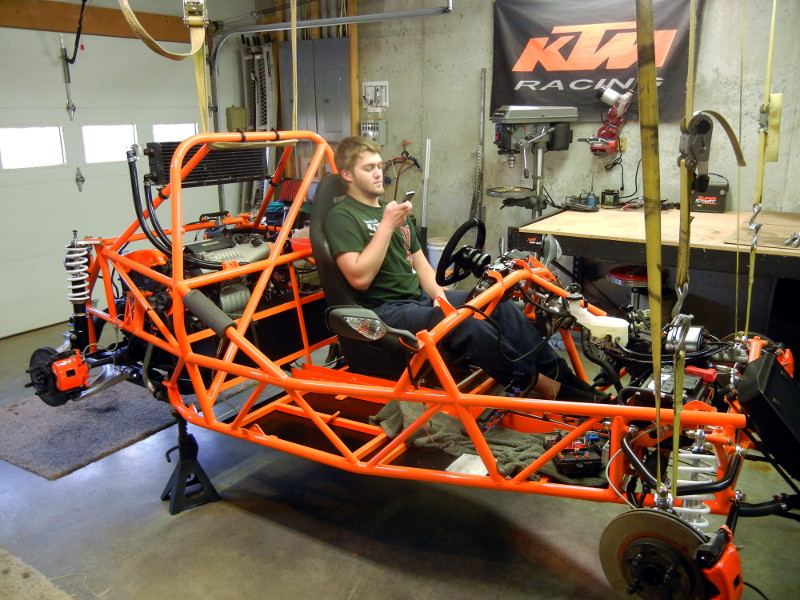
This is the very first start attempt since the accident. I didn't have any known reason to suspect it would not start, but with some of the wiring damage up front, I was not positive. I was just hoping that it would and everything would be good and no major issue. Needless to say, I was very happy, much like the first time!
Today we mounted the rear solid engine mount, tunnel cover, shifter, and put muffler back on. I had already added the oil and coolant and finished up the required wiring to start the engine for the first time again.
He's not on his phone but recording a video to send to his friends at school.
This is the very first start attempt since the accident. I didn't have any known reason to suspect it would not start, but with some of the wiring damage up front, I was not positive. I was just hoping that it would and everything would be good and no major issue. Needless to say, I was very happy, much like the first time!
Last edited:
ctuinstra
Goblin Guru
We have been working here and there on the car over the holidays. Kaleb finished up the wiring in the front for the headlights, fan, and horn. Today we adjusted the suspension, fine tuned the steering center and did a preliminary wheel alignment. Kaleb is going to take it in tomorrow to get it aligned. It's now on the ground.