Intercooler pump and related fan

Steve Sallenbach

Active Member
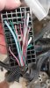
What wires are you using to run the intercooler pump and the fan? I left some of the red w/white striped wires from either the BCM or ECM multi-plugs in case I needed them for some reason. I left a good portion of two of the big red wires coming out of the large white multi-plug but I think they are tied to 30 plus amp fuses... probably more than I need. I have a couple of red or red w/white wires coming out of the BCM but like a dummy I forgot to make a note what they went too.
 

ctuinstra

Goblin Guru
Trace them back to the BCM connector and tell us which pin and connector it is. You can also look them up in the Chilton manual (search the forum for it)
 

Briann1177

Goblin Guru
I don't know about other models, but I noticed with mine the pink wires are typically ignition switched. There are exceptions, but that was a trend i saw. The red wires may or not be so I'd double check.
 

Brian74

Goblin Guru
Not the BCM. Leave the BCM alone. The fan circuits are switched on by the ECM. Fan one trigger is a green wire; fan 2 trigger is a blue wire. Regardless, these circuits are grounded by the ECM in order to provide power to the fan relays (lt. blue & gray 12 gauge wires). 2007 & below also has its own dedicated intercooler pump relay. 30 amps is plenty to run the pump & fan. You can run either of the fan relay trigger wires to ground to run the fan at all times when the key is on. I recommend letting the ECM run the COOL FAN relay 1 with the Goblin radiator and grounding the blue COOL fan relay 2 to run your intercooler fan & pump.
0E9046A7-9863-457B-8739-F816FC18C960.jpeg
 

Briann1177

Goblin Guru
The top side of the cooling fan relays are connected to B+ voltage. If you ground out the wires on pins 45 & 46, then the fan will run regardless of ignition status. You'll basically end up with a straight hot wire from the battery.

At least that's my understanding of the power distribution schematics. I could be wrong. I'd rather use a circuit that I know is connected directly to the run/crank relay.
 

Briann1177

Goblin Guru
Maybe I'm not following. Pins 85 and 30 on the cool fan 2 relay should be always hot regardless of the position of the ignition switch because they're both connected to B+. If you ground out the dark blue wire (473) right where you have it highlighted, the cool fan 2 relay will be constantly closed and send battery voltage through the 30A fuse, through the relay, and out the gray wire.

Power_Distro.jpg
 

Brian74

Goblin Guru
I stand corrected on the battery voltage being direct to the fan relay. Thanks for pointing that out. I still wouldn’t use the run/crank relay though. If a fan motor shorts out later on, you will find yourself stuck with no way to diagnose the issue vs. a blown fan fuse. Also, those fan motors draw significant amperage. The best way to do it would be to wire in an additional relay near the power dist. block that switches to ground when the key is on, and use that relay to ground the fan relay trigger.
 

Brian74

Goblin Guru
I’m running up to Phoenix to literally wire up this circuit today. I’ll take pics and explain how I did it. Will probably use either the ABS2 or BCK UP wires from the power dist block as the key on relay trigger, but the actual circuit will remain on the fan relay and all will be done at the power dist block.
 

Briann1177

Goblin Guru
That's a good point. There are sub-circuits connected to the run/crank that should in theory blow their fuse before affecting the 30A crank fuse.
 

Steve Sallenbach

Active Member
Thanks guys for all the good info, I really appreciate all the help! I figured you or someone has this figured out so I don't have to recreate the wheel again. This site is great with everyone helping each other out. Brian74, if you could let me know when it's convenient how your wiring went at Phoenix. Thanks Steve
 

Brian74

Goblin Guru
I ended up running the pink ABS 2 wire from the C5 fusebox connector to a relay. When key is turned on, relay kicks closed & provides ground to the blue fan relay trigger wire. Works great.
We can now run the HE fan and coolant pump directly off the engine harness fan 2 connector.
 

SliderR1

Well-Known Member
Probably worth noting that this is for a Turbo car. Do the turbo cars have an intercooler pump from the factory? I was thinking they were air to air cooled...
 

Steve Sallenbach

Active Member
Just to clarify so I don't screw something up, I attached pictures of both fan wires... the passenger side fan #2 (I think) is the gray with a black ground that connects to the engine. The drivers side (fan 1) is the light blue and white wire. The gray, lite-blue and white wires goto the large black multi-plug.
I can cut the blue wire at the plug connection and solder it to the black wire that is references in the build guide. I need to ground the white wire since it goes to the fan relay switch which grounds the circuit. The gray wire can be hooked to the positive wires on both the pump and inter-cooler fan. Black wire to a ground or do I add in a new relay using the ABS wire Brian74 talks about?
 

Attachments

Waterdriver

Goblin Guru
I stand corrected on the battery voltage being direct to the fan relay. Thanks for pointing that out. I still wouldn’t use the run/crank relay though. If a fan motor shorts out later on, you will find yourself stuck with no way to diagnose the issue vs. a blown fan fuse. Also, those fan motors draw significant amperage. The best way to do it would be to wire in an additional relay near the power dist. block that switches to ground when the key is on, and use that relay to ground the fan relay trigger.
For the SC cars, can we use the HE pump power wire as the relay trigger for the HE fan relay?
I kind of like the fact the HE pump is on a "power on" delay from engine start.
 
Top