JS City Goblin - 2010 LS

JSATX

Goblin Guru
Thanks. But I had to take a break from that before the chainsaw came out aimed at that wiring bundle.

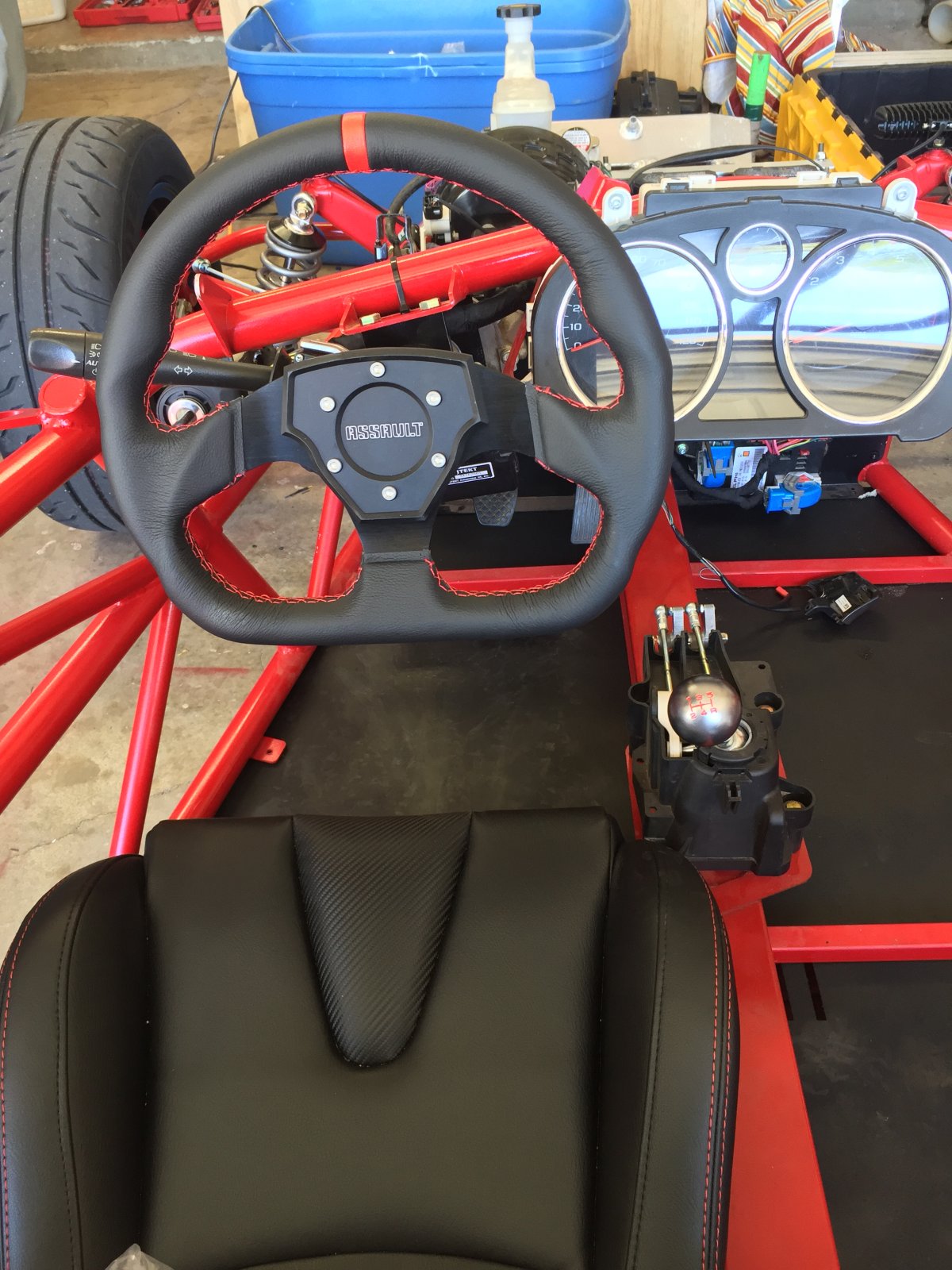
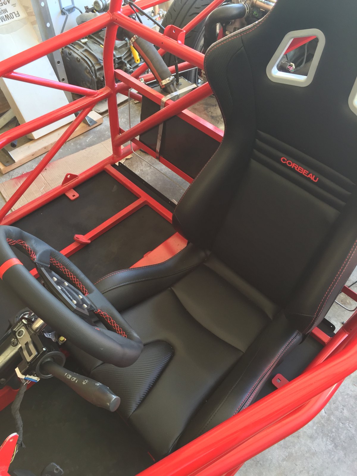
So tidying up the "interior." Got my new steering wheel installed. It matches the seats perfectly and makes getting in and out easier. Super happy with the way it looks and feels.

IMG_7385.JPG


IMG_7386.JPG
 

JSATX

Goblin Guru
The goblin we are testing on is only up to first stage. We have not hooked up any lights of any type yet.
The turn signal only works when the key is on.

The only way we know the turn signal is working is by the arrows on the cluster.

You should try jumping from pin g or h on the turn signal plug to the negative post of your battery. This will eliminate a possible ground issues.
Ok good news but I'm not sure what it means. I hooked a jump wire directly to the battery ground and touched it directly to Pin G just like you said and the blinker worked!!

HOWEVER, when I check continuity between the ground wire (pin B) I get ground. So my ground wire is hooked up correctly. So confusing.

So the next step was to check the turn signal stalk. I put my meter on ohms between pins B and G. Blinker stalk off there is no connection. Turn blinker to on and it goes to 0 ohm. So that's working correctly as well! What the heck.
 

JSATX

Goblin Guru
Ok good news but I'm not sure what it means. I hooked a jump wire directly to the battery ground and touched it directly to Pin G just like you said and the blinker worked!!

HOWEVER, when I check continuity between the ground wire (pin B) I get ground. So my ground wire is hooked up correctly. So confusing.

So the next step was to check the turn signal stalk. I put my meter on ohms between pins B and G. Blinker stalk off there is no connection. Turn blinker to on and it goes to 0 ohm. So that's working correctly as well! What the heck.
WRONG!! I remembered checking the ground wire but I had checked the ground wire going into the second 4 wire plug into the turn stalk! Pin B on the flat connector wasn't connected to ground!!

I cut out the wire and touched it to the steering shaft bolt AND I HAVE MOTHERLOVIN TURN SIGNALS. Finally!!

Of course I had already carefully bundled all the wires in many feet of tape and zipped them to the frame. So that's coming off.

Kids if you learn anything from this thread it's don't bundle your **** wires until everything is tested and functioning correctly.
 
Last edited:

JSATX

Goblin Guru
Congrats on getting that figured out Justin! I'm envious of how far you are!

Nuker-
Thanks! Truth is I'm just so determined to get it legal as quickly as possible. Ive been spending even more time on it than usual lately because the weather has been so nice and I just want to go for a drive so badly.
 

JSATX

Goblin Guru
Side project I've still been playing with.

This is nothing more than a proof of concept. The software worked well! We currently have a 50us delay on the data transfer. Will be playing with that and different housings over the next few days. The lights require different voltages per color, we have them all getting the same voltage so that's why the yellow is so dim.


Sorry the video quality is bad.
 

JSATX

Goblin Guru
Lonny / Adam,

Any problem with shortening the steering column tube? Because I can't not mess with stuff, I've added an adapter and a QD to my wheel which pushes it just a little too far forward. I've studied it for a while and seems really straight forward. I'd just like to shorten the tube by 1" and redrill the three holes. But wanted to ask first in case I'm not seeing a potential problem.

IMG_7398.JPG
 

JSATX

Goblin Guru
From what I read I have to replace my headlights for inspection, as they need to have a bright function and my LED lights do not.

So I whipped up a little bracket to hold the cheap dominator style lights in place. Spent all of ten minutes drawing it up and I actually really like it. It holds the light snug. I'm installing a steel standoff in the base of it to screw against the frame.

IMG_7414.JPG

IMG_7415.JPG


Honestly I'll end up throwing my LEDs back on later because I like the way they look a lot. But these will do for now.
 

JSATX

Goblin Guru
Haven't really done a whole lot lately. It's just about to the point where I could take it to the inspection. Installed and wired the mirrors but haven't actually mounted them. Just wanted to see the signals work. I found a random shelf bracket that happened to have the correct hole spacing and threw that on there so the mirrors wouldn't fall off.

IMG_7423.JPG


Also got the harness in. I'm not sure what's the best way to bolt it to the frame. It didn't come with nuts and it's a fine pitch not easily found. Basically you get this special bolt with a shoulder on it, a spacer, and a lock washer. I assumed I didn't want to bolt the belt right up against the frame so I put the spacer between.

There's probably a better way to do this?

IMG_7424.JPG
 

DanPerryy

Well-Known Member
WRONG!! I remembered checking the ground wire but I had checked the ground wire going into the second 4 wire plug into the turn stalk! Pin B on the flat connector wasn't connected to ground!!

I cut out the wire and touched it to the steering shaft bolt AND I HAVE MOTHERLOVIN TURN SIGNALS. Finally!!

Of course I had already carefully bundled all the wires in many feet of tape and zipped them to the frame. So that's coming off.

Kids if you learn anything from this thread it's don't bundle your **** wires until everything is tested and functioning correctly.
One thing I did on my wiring was to interconnect all the ground lugs with a wire so I was assured that all would be grounded regardless of fastening to chassis. So far everything has worked first time.
 

JSATX

Goblin Guru
One thing I did on my wiring was to interconnect all the ground lugs with a wire so I was assured that all would be grounded regardless of fastening to chassis. So far everything has worked first time.
That's a great idea. I didn't think far enough ahead when doing the wiring. Because I knew the chassis was grounded I kinda went the opposite direction. I cut a lot of the ground wires out and have several ground points throughout the frame. I have each headlight grounded to each side of the radiator mount, the ignition grounded to the screw holding it to the frame...etc etc
 

JSATX

Goblin Guru
After getting the mirrors and seat harness installed I went for another jaunt around the back of the neighborhood. This time I focused on practicing rapid braking. Second gear gets me to just over 60mph and I could get it down to stopped pretty quickly.

The very first time I braked hard the front got really squirrelly. It shook so bad I went home to try and figure out what happened. Everything was still tight, my guess is I don't have a very good bleed job, one of the tires was getting a lot more braking force than the other causing the upset. I've had good luck just using my Mityvac brake bleeder in the past but I think the bleeder valves on these calipers is letting too much air in through the threads when I use it. So next time I have a friend over I'll bleed all four in a more traditional manor and I think it'll be much better.

One thing I will say to anyone who doesn't have a fair bit of experience on non ABS controlled vehicles...practice!! In a panic situation it's going to be extremely easy to lock the fronts and potentially ruin your tires.
 

JSATX

Goblin Guru
Haven't really done a whole lot lately. It's just about to the point where I could take it to the inspection. Installed and wired the mirrors but haven't actually mounted them. Just wanted to see the signals work. I found a random shelf bracket that happened to have the correct hole spacing and threw that on there so the mirrors wouldn't fall off.

View attachment 809

Also got the harness in. I'm not sure what's the best way to bolt it to the frame. It didn't come with nuts and it's a fine pitch not easily found. Basically you get this special bolt with a shoulder on it, a spacer, and a lock washer. I assumed I didn't want to bolt the belt right up against the frame so I put the spacer between.

There's probably a better way to do this?

View attachment 810

So I called Corbeau. The bolt they supplied is threaded 7/16-20. But it's marked 10.9. I've never seen a standard thread bolt with metric markings!
 

JSATX

Goblin Guru
Well finished up the wiring tonight. I replaced my LED headlights with the dominators so I could pass inspection. Turn signals, lows, brights, parking, brake, everything working perfectly.
IMG_7442.JPG
 

JSATX

Goblin Guru
Did a little inspection today. Basically went from front to back checking torque values of any bolts I could get to.

I noticed there appears to be one missing! I dont see any threads, but you can tell from the polished area of the engine material it appears there used to be a bolt there.

So, is there supposed to be a bolt here? It's Immediately below the water pump tube next to thermostat and cylinder #4 exhaust.

IMG_7453.JPG


IMG_7452.JPG
 

DanPerryy

Well-Known Member
I think it is a transmission bolt, holding the engine and trans together. This one was one that I had a hard time finding when I was trying to pull the original AT off my engine.
 

JSATX

Goblin Guru
Does anyone have any info on what would be the most convenient switched power wire to tap into? Installing an AFR gauge and I want it to turn off and on with the key.
 
Top