ncgoblin's Build Thread - 2005 SS/SC North Carolina

ncgoblin

Goblin Guru
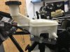
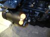
Calling all supercharged owners. I am about to start installing the heat exchanger, and radiator piping on the engine. I could really use some visuals of how to install this hardware. I have browsed the forum and it seems most of you customised from the base kit. A zoomed out photo of the engine to pump would help. Also I believe these (2) white 6-7' PVC go from front to rear so is the heat exchanger bolted behind the radiator?

Thanks!
 

Lonny

Administrator
Staff member
20180321_162412.jpg

It bolts horizontal on a one inch crossmember with a fan mounted on top.

20180821_151403.jpg

This is with the optional air duct.
20180821_151145.jpg
 

ncgoblin

Goblin Guru
Only piece I am missing now is heat exchanger piped into the engine I will do some more research today I have a few pieces of the puzzle but not the complete route.

In the meantime here are some photos of progress so far.

AC Compressor gutted inside. I kept the entire housing for structural support and the weight was cut 3x since the internals were removed so that is good. The pulley also is much smoother now. I used RTV silicone to cover up the AC line holes and painted with East Coast Body Black.

IMG_0487.JPG


I assume this is the EVAP adapter is it required? If not do I just run the lines without the plug?

IMG_0505.JPG
IMG_0506.JPG


Engine is going back together I used East Coast Ceramic paint for the engine/charger. Valve cover is powder coated in a candy apple red that has a hint of gold when the sun hits it. The brake calipers match excited to see those up against the flat black wheels.

IMG_0507.JPG
 

Waterdriver

Goblin Guru
Here is a picture of the HE coolant line routing.
Screenshot_20180918-141702_Drive.jpg


If your using the stock IC endplate:
-Connect one of the lines coming from the HE to the middle coolant line nipples on the IC endplate.
- The two othe IC endplate coolant line nipples should connect together like in the picture and run down to the IC pumps end (intake) nipple.
- The IC pumps discharge nipple (coming out the side of the pump) goes to the other line going back to the HE.

Edit: Note: The HE coolant system is completely separate/isolated from the engine cooling system.

Hope this helps out.
 
Last edited:

ctuinstra

Goblin Guru
AC Compressor gutted inside. I kept the entire housing for structural support and the weight was cut 3x since the internals were removed so that is good. The pulley also is much smoother now. I used RTV silicone to cover up the AC line holes and painted with East Coast Body Black.
If you are interested, Kaleb made a designed and 3D printed a plug for the compressor.

DSCN0954.JPG
 

Attachments

ctuinstra

Goblin Guru
I can't upload that file type here. I created an account on thingiverse to upload them there but I have to wait 24 hours. Don't let me forget to upload and publish them.
 

ncgoblin

Goblin Guru
Here is a picture of the HE coolant line routing.
View attachment 5301

If your using the stock IC endplate:
-Connect one of the lines coming from the HE to the middle coolant line nipples on the IC endplate.
- The two othe IC endplate coolant line nipples should connect together like in the picture and run down to the IC pumps end (intake) nipple.
- The IC pumps discharge nipple (coming out the side of the pump) goes to the other line going back to the HE.

Edit: Note: The HE coolant system is completely separate/isolated from the engine cooling system.

Hope this helps out.
I assume the IC is the small coolant tank attached to the supercharged? Also during the front end crash this tank bracket snapped off. Are we able to use the stock coolant tank for the charger or will it touch the frame?
 

ctuinstra

Goblin Guru
I assume the IC is the small coolant tank attached to the supercharged? Also during the front end crash this tank bracket snapped off. Are we able to use the stock coolant tank for the charger or will it touch the frame?
The IC is the intercooler. The end plate is the plate on the side of the intake where the hoses connect to. The stock end plate has only two ports while the dual-pass plate has three allowing for a different coolant route.

https://zzperformance.com/collections/ecotec/products/zzp-lsj-dual-pass-intercooler-plate-kit

1537326588149.png
 

ncgoblin

Goblin Guru
The IC is the intercooler. The end plate is the plate on the side of the intake where the hoses connect to. The stock end plate has only two ports while the dual-pass plate has three allowing for a different coolant route.

https://zzperformance.com/collections/ecotec/products/zzp-lsj-dual-pass-intercooler-plate-kit

View attachment 5306
Ok now it makes sense when I upgrade my pulley in the future I will get this setup. So if I am understanding WaterDrivers post the stock supercharger small coolant tank is not required?
 

Waterdriver

Goblin Guru
The IC is the intercooler. The end plate is the plate on the side of the intake where the hoses connect to. The stock end plate has only two ports while the dual-pass plate has three allowing for a different coolant route.

https://zzperformance.com/collections/ecotec/products/zzp-lsj-dual-pass-intercooler-plate-kit

View attachment 5306
That is correct. The stock Cobalt system just had a filler neck with no reservoir tank. The picture I posted is with the "Option B" tank for the Heatexchanger system. Which is similar in shape and size to the Cobalt engine coolant reservoir tank. Just to make things more confusing.
 
Top