SS Model Heat Exhanger Fan Wiring
- Thread starter SliderR1
- Start date
Briann1177
Goblin Guru
Not sure how the SCs work, but Lonny said you'd have to find your own power source for the TC's water pump.
If that's the case for you, you'll probably have some unused fuses to pull power. Im going to use the now free ABS fuse since it's tied to the run/crank relay.
If that's the case for you, you'll probably have some unused fuses to pull power. Im going to use the now free ABS fuse since it's tied to the run/crank relay.
Briann1177
Goblin Guru
I thought about using the second fan relay too, but that got me thinking. For the TCs, the second fan comes on when the coolant temp is > 230 degree F. I think the SCs are similar. Under boost that air charge will begin to heat up the water and there wouldn't be as much air flow if the coolant temp is < 230 degrees.
Last edited:
SliderR1
Well-Known Member
I didn't write a thorough enough explanation of what I had in mind. I was going to rewire the input signals on the second fan relay so it is triggered when the cooling pump comes on, not from its original input from the PCM - and hence will have nothing to do with the actual engine coolant system.
With this re-wire concept, if the HE pump is running, the fan will also be running. Just a concept for now - I'm looking over the wiring schematics to see how big of a headache it will be to re-wire the second fan relay. Either way, I will end up with a relay that will be triggered by the HE pump - I think that is the best trigger to turn on the HE fan.
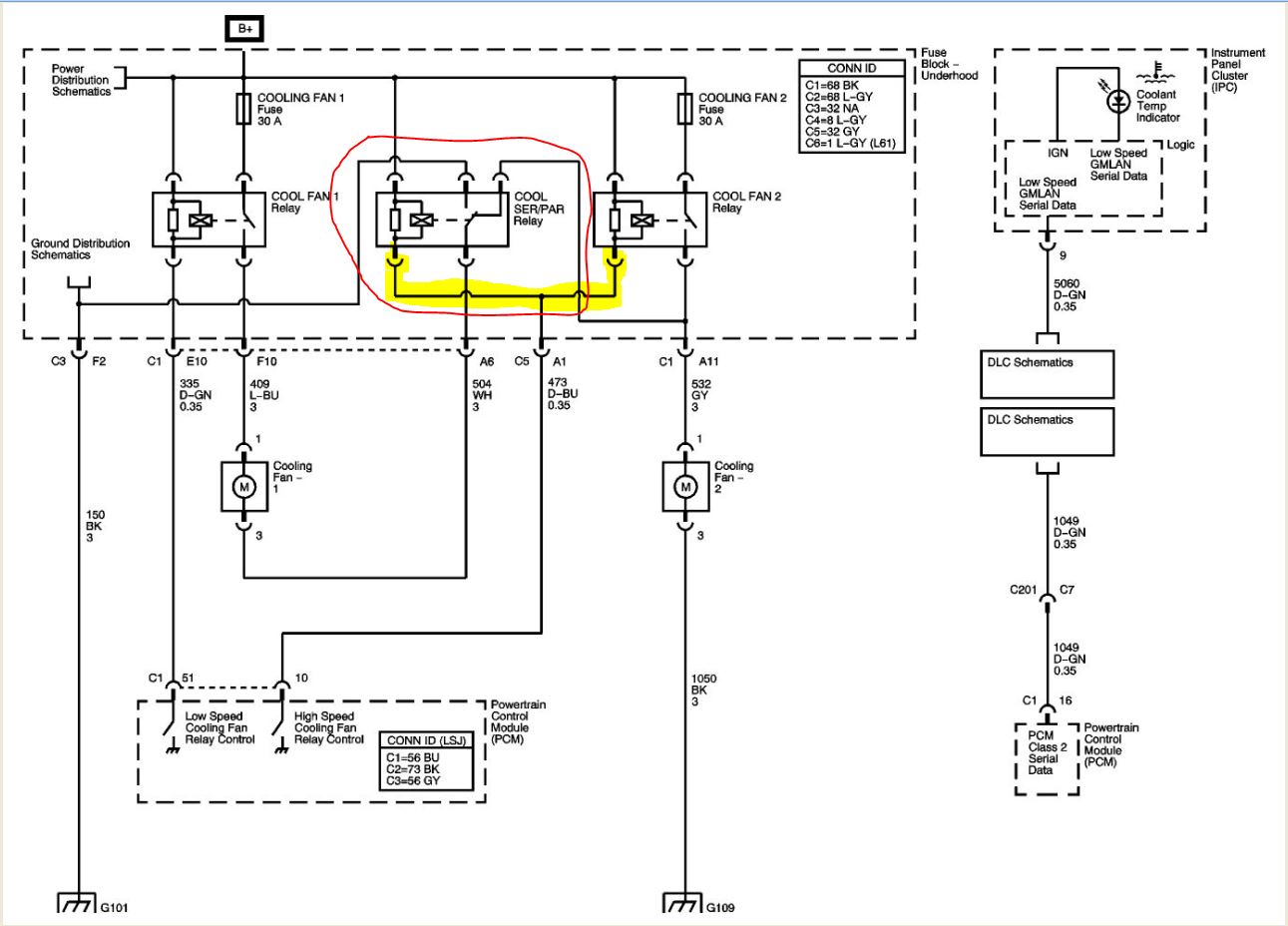
One thing I haven't figured out yet is what "COOL SER/PAR Relay" is for... I need to confirm that is or isn't needed for the primary fan to work. The ground on this diagram has effectively been removed from the way we are wiring up the primary fan on the Goblin, so my thinking is that it isn't necessary...please correct me if I'm off...
I would like to be able to take the wire highlighted in yellow and connect it to the input signal for the HE pump and get the second fan to run off that... The other connection second connection from COOL SER/PAR Relay, I need to figure that one out, too...maybe just a disconnect...
With this re-wire concept, if the HE pump is running, the fan will also be running. Just a concept for now - I'm looking over the wiring schematics to see how big of a headache it will be to re-wire the second fan relay. Either way, I will end up with a relay that will be triggered by the HE pump - I think that is the best trigger to turn on the HE fan.
One thing I haven't figured out yet is what "COOL SER/PAR Relay" is for... I need to confirm that is or isn't needed for the primary fan to work. The ground on this diagram has effectively been removed from the way we are wiring up the primary fan on the Goblin, so my thinking is that it isn't necessary...please correct me if I'm off...
I would like to be able to take the wire highlighted in yellow and connect it to the input signal for the HE pump and get the second fan to run off that... The other connection second connection from COOL SER/PAR Relay, I need to figure that one out, too...maybe just a disconnect...
Attachments
-
 121.9 KB Views: 367
Briann1177
Goblin Guru
Yeah, I realized that as soon as you posted the schematic. I forgot.
If I understand you correctly, your goal is to have the HE fan run when the water pump is running, right? How are you planning to power the water pump? The wire you have highlighted in yellow is just a switched ground wire. You'll still need battery power from somewhere.
If I understand you correctly, your goal is to have the HE fan run when the water pump is running, right? How are you planning to power the water pump? The wire you have highlighted in yellow is just a switched ground wire. You'll still need battery power from somewhere.
SliderR1
Well-Known Member
Power for the pump won't change. The only thing that will change on that system is the splice in of the yellow line on the diagram I posted. That way when the pump is active, it will trigger the HE relay (old cooling fan 2).
For the HE fan circuit, I will leave the relay in the fuse box and keep both power feeds as-is. I'll extend the Gray wire from the cooling fan 2 relay to the actual fan and eliminate the splice back to the SER/PAR relay.
I'll draw up a sketch later this evening.
For the HE fan circuit, I will leave the relay in the fuse box and keep both power feeds as-is. I'll extend the Gray wire from the cooling fan 2 relay to the actual fan and eliminate the splice back to the SER/PAR relay.
I'll draw up a sketch later this evening.
Last edited:
Briann1177
Goblin Guru
OK. I think what cutinstra said made it click for me. Should be pretty easy in theory. Take your water pump power wire and run it to the top side of the cooling fan 2 relay. Then take the ground wire off of the ser/par relay and just ground it out to the frame. Hooking your HE fan up to the gray wire, ground the other fan wire to the frame, and you should be done.
The tricky part is I don't think the backside of the fuse box module has wires or anything else easy that you can get to and rearrange. I haven't pulled mine apart so I don't really know what would be involved.
The tricky part is I don't think the backside of the fuse box module has wires or anything else easy that you can get to and rearrange. I haven't pulled mine apart so I don't really know what would be involved.
Last edited:
ctuinstra
Goblin Guru
I could help you with that. You could also take the ground signal from the inter cooler water pump to drive the fan really 2. Then the the relay can power the fan.
The ser/par relay can be pulled out and then jumper the ground through it to provide ground to fan 1. I'll have to draw it out later to make more sense.
The ser/par relay can be pulled out and then jumper the ground through it to provide ground to fan 1. I'll have to draw it out later to make more sense.
SliderR1
Well-Known Member
So, I think I have confirmed all the circuits and connections needed to make this work and I'm going to post some diagrams for you guys to scrutinize. Yellow highlights are removals.
From my research, I need to replace existing circuit 473 with a splice from circuit 2022. I need to investigate the lid to the fuse box a little more closely when I get home to confirm the best way to physically connect that splice into the old cooling fan relay circuit.
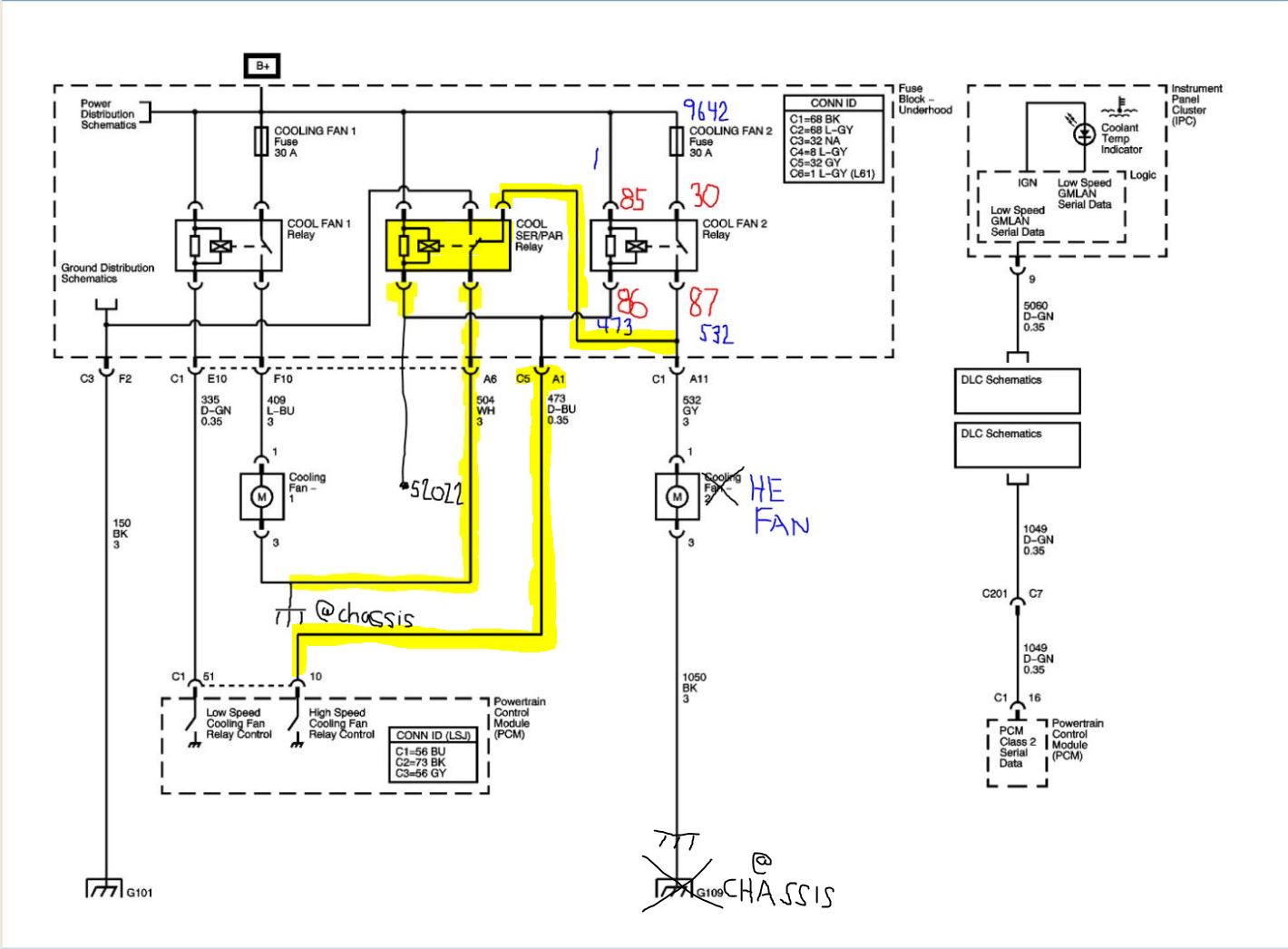
From my research, I need to replace existing circuit 473 with a splice from circuit 2022. I need to investigate the lid to the fuse box a little more closely when I get home to confirm the best way to physically connect that splice into the old cooling fan relay circuit.
Briann1177
Goblin Guru
That should work. You'll have to break the B+ connection to the top side of the cooling fan 2 relay and wire in circuit 2022 for the pump supply voltage. Otherwise your fan won't shut off until your battery is dead.
Briann1177
Goblin Guru
Also please take pics on how you'll deal with the fuse box connections. I wanted to do something very similar for my water pump but couldn't figure out a good way to deal with the backside fuse connectios.
ctuinstra
Goblin Guru
It won't quite work they way you have it. If you tie 86 of the relay to 2022, you will be supplying 12v where it needs a ground. The Cool Fan 2 relay is ground switched, so you need to supply a ground to energize the relay (it always has 12v).
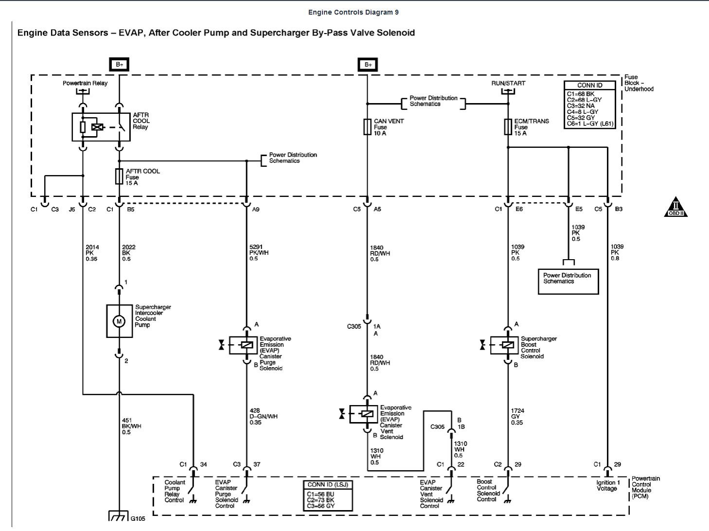
You could hook 86 to 2014. This way when the PCM energizes the AFTR COOL relay, it will also energize the HE fan relay.
Remove the COOL AER/PAR relay and jumper across it here to provide a permanent ground for the cooling fan 1 (use very heavy gauge wire and good spade connectors). Cut wire 473 (D-BU). That's about all you would have to do. Hooking 86 to 2014 would be fun to find and connect. Wire the HE fan up to 532 (GY) like you have it drawn.
Briann1177
Goblin Guru
Good catch about 2022. I think using the ground side like ctuinstra said is probably the better way to go. That way you're running a ground wire instead of cutting a positive trace or whatever is in the fuse box.
Last edited:
SliderR1
Well-Known Member
ctuinstra - thanks! After posting that, I did realize what you both pointed out. It needs a ground, not a +12v. I agree what you have proposed should work. I also think it will be easier to wire up. I should be able to route a spliced jumper from the 2014 circuit (PK wire) C5-C2 pin in the fuse block to the C5 - A1 pin. Both of these have actual pins in the block - so I won't have to get into the circuit board on the top of the fuse block under the relays/fuses - which is where all the connections to the actual relay for Cooling Fan 2 are located.
I do have one question on your suggestion. I don't understand why we would need to jump, or even keep, the SER/PAR relay. The way we are wiring up cooling fan 1, the ground is going to the chassis up on the front of the Goblin, which eliminates the ground circuit (504) that was originally going to the SER/PAR relay. Also, if the relay is still in place, it will be nearly impossible to break the connection from the SER/PAR relay to the 532 circuit as it is etched on the circuit board. Wouldn't just removing the relay fix this problem?
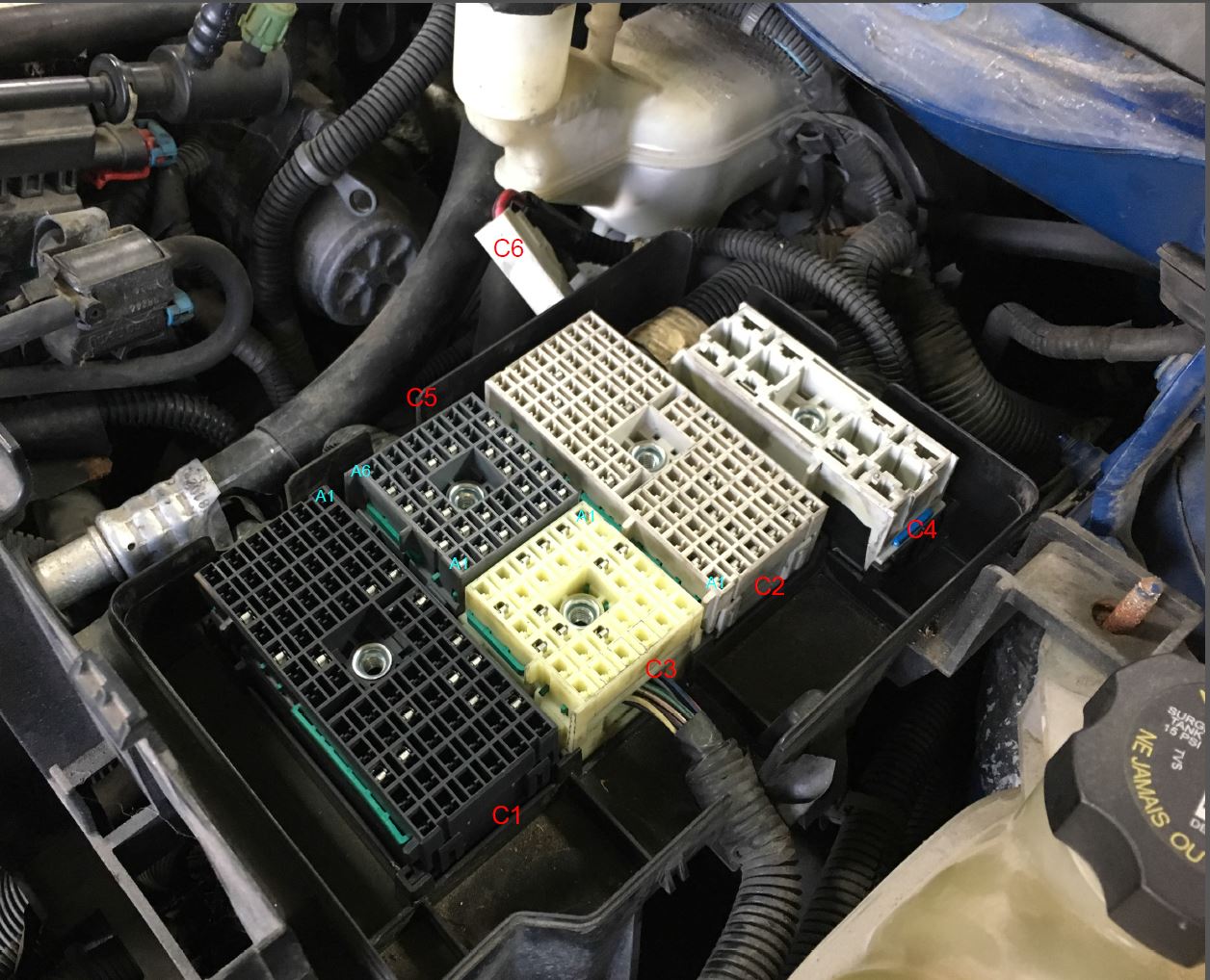
Here is a picture of the fuse box connectors with labels:
I do have one question on your suggestion. I don't understand why we would need to jump, or even keep, the SER/PAR relay. The way we are wiring up cooling fan 1, the ground is going to the chassis up on the front of the Goblin, which eliminates the ground circuit (504) that was originally going to the SER/PAR relay. Also, if the relay is still in place, it will be nearly impossible to break the connection from the SER/PAR relay to the 532 circuit as it is etched on the circuit board. Wouldn't just removing the relay fix this problem?
Here is a picture of the fuse box connectors with labels:
Last edited:
Briann1177
Goblin Guru
That's an interesting idea. Are your thoughts to drop the high temperature setting so that they both run continuously in high speed mode?