Turbo Plumbing

Briann1177

Goblin Guru
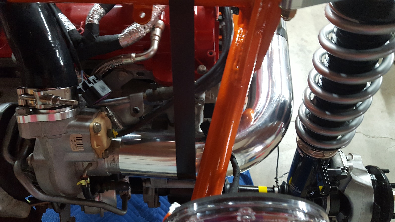
It doesn't appear that there is enough clearance to route the turbo intake tube between the frame and the rear coilover. The reducer boot adds a good 2" or so to how far it sticks out and there is no way I can see of how it can clear the coilover. Here's a picture of it without the boot. It would clear just fine if there was a way to directly attach the tube to the inlet on the turbo without any silicone boot.

What am I missing?

Brian_Turbo.jpg
 
Last edited:

Lonny

Administrator
Staff member
It looks like that tube got out before being trimmed. You will need to cut.
1530533397201969542814.jpg

It needs to be between 9 to 9.5 inches.
15305331310281748029117.jpg

It also helps to angle it down as much as you can.
 

Briann1177

Goblin Guru
Mine is already cut to exactly 9.5". Are there any potential issues with doing something like this? For example, fender mounts, MAF sensor performance issues, road debris, etc? I'm having a hard time envisioning how the clearance will change once it's on the ground and everything is adjusted, but it looks like things are mostly clear.

20180702_080824.jpg
 

Briann1177

Goblin Guru
I think I can get it to work as mostly intended. I don't like having the intake filter that close to the back tire.
 

Lonny

Administrator
Staff member
We tried to run a filter close to the turbo and could not get the maf to read correctly. We found information that said the turbo creates a vortex that affects the air several inches ahead of the turbo.
This is why we moved the maf as far ahead of the turbo as we could.
9.5 inches is on the long side and you really have to set it deep in the silicone boot. It will help to trim a little more off. We will probably start shooting for 9 inches.
When you angle it down it also moves it away from the strut.
 

Briann1177

Goblin Guru
I hack sawed about 1" off, and I think that will work. After doing some dry fitting I was having a lot of issues trying to find a good way to run the filter inside of the frame. With my heat exchanger water pump sitting right where the A/C compressor used to be, I just couldn't find a good way to route it.

So in the end, this is what I came up with. I was a little concerned at first about water with the intake angled up, but I see builds where it's pointing straight up. I have another silicone boot on order so the actual MAF tube isn't connected just yet.

I really hope there are no major changes in clearance and positioning once everything is on the ground and adjusted.

Rear_Turbo.jpg


20180702_145929.jpg
 

Briann1177

Goblin Guru
No need to halt production on the intake tubes and redesign everything because I got it to fit as designed. I think my biggest problem was my coilovers weren't adjusted and the axles were pointing up. Once I roughed them in so the axles were closer to level, I have a lot more room. Plus I think shortening it by 1" helped quite a bit.

What is the screw size for the MAF sensor? 6-32 or are they metric?
 
Top