'07 LSJ MAP sensor pinout?

devianteng

Well-Known Member
So I have one last DTC I'm sorting through; P0107 - "Manifold Absolute Pressure/BARO Sensor Low". I pulled a log with HPT and confirmed I don't have any readings from the MAP sensor, but I do have IAT2 sensor reading (which is on the same MAP sensor). So either my sensor is partially bad (still able to read IAT2 but not pressure), or I have a wiring issue. New sensor on ordered, but I have the engine harness out so want to double check continuity across the MAP sensor connector.
316008383_471709688175725_4199997913736268236_n.jpg

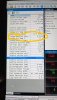
I was able to get a screenshot from GMSI for a 06 showing pinout of the MAP sensor:
315517762_2681333671996922_7373914480763385118_n.jpg

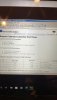
And found a PCM pinout from a 05 SS/SC on CSS.net, and figured out where 3 of the MAP connector pins go:
Pin 1 goes to pin 20, PCM C2
Pin 3 goes to pin 8, PCM C2
Pin 4 goes to pin 37, PCM C2

All three of those wires test continuity just fine, so things should be good. However Pin 2, according to what I found for the 05 SS/SC, that goes to pin 14 on PCM C1; PCM C1 is the PCM connector on the body harness, so this makes no sense to me at all. PCM C2 and C3 are the 2 PCM connectors on the engine harness.

I previously taped up my engine harness with Tesa tape, so it's a pain in the butt to untape and trace that L-BU wire manually so I'm hoping to find a better diagram for my 07 that tells me where that should go so I can test it. According to the 06 SS/SC GMSI info I have, it's Circuit No. 6118, "IAT 2 Sensor Signal".

Like I said above, I am getting an IAT2 reading in HPT and it's the MAP reading I'm not getting -- Pin 4, Circuit No. 6337 is "MAP Sensor Signal" and I'm getting continuity on from pin 4 of the MAP to pin 37, PCM C2 as expected so I should be good but want to be absolutely positive.


Anyone have 07 LSJ wiring diagrams, or access to GMSI (better yet, anyone have the GMSI virtual machine that they'd be willing to share?)

Thanks!
 

Ross

Goblin Guru
AllDataDIY has a slightly different discription for the P0107... it claims the error is on the other MAP sensor... the one on the intake, with the intake air temp sensor 2 built into it. Not sure if AllDataDIY is right... or if it the the other MAP sensor with the Barometric pressure.
Ross.

AllDataDIY:
DTC P0107 Manifold Absolute Pressure (MAP) Sensor Circuit Low Voltage
The PCM detects that the MAP sensor signal voltage is less than 0.1 volts for more than 2 seconds .

CIRCUIT DESCRIPTION
The manifold absolute pressure (MAP) sensor that resides in the engine intake manifold is integrated with the intake air temperature (IAT) sensor 2. The purpose of this integrated sensor is to measure the following:

  • The atmospheric pressure and the vacuum or the reduced pressure that exists under different operating conditions in the engine intake manifold
  • The supercharged air pressure that exists under high load or wide open throttle conditions in the engine intake manifold
  • The IAT 2 after the supercharger and the intercooler as it enters the engine intake manifold
  • The IAT 2 after the supercharger bypass valve and the intercooler as it enters the engine intake manifold
The MAP/IAT sensor 2 has the following types of circuits:

  • A powertrain control module (PCM) supplied and regulated MAP 5-volt reference circuit
  • A PCM supplied ground for the low reference circuit that is shared by the MAP and the IAT sensor 2
  • A MAP sensor signal circuit that supplies a voltage input to the PCM
  • A PCM supplied 5-volt , IAT signal circuit
The diaphragm within the MAP sensor responds to all of the various pressure changes in the intake manifold, and provides a signal voltage to the PCM on the signal circuit, relative to those pressure changes.

The PCM monitors the MAP sensor signal for voltage that is outside of the normal range of a properly operating sensor. If the PCM detects a MAP sensor signal voltage that is excessively low, DTC P0107 sets.

DTC DESCRIPTOR
This diagnostic procedure supports the following DTC:
DTC P0107 Manifold Absolute Pressure (MAP) Sensor Circuit Low Voltage

CONDITIONS FOR RUNNING THE DTC

  • DTCs P0120, P0121, P0220, P0641, P0651, P2135 are not set.
  • The engine is cranking or running.
  • The TP Indicated Angle parameter is more than 0 percent , when the engine speed is less than 1,100 RPM .OR
  • The TP Indicated Angle parameter is more than 10 percent , when the engine speed is more than 1,100 RPM .
  • DTC P0107 runs continuously when the above conditions are met.
CONDITIONS FOR SETTING THE DTC
The PCM detects that the MAP sensor signal voltage is less than 0.1 volts for more than 2 seconds .

ACTION TAKEN WHEN THE DTC SETS

  • The control module illuminates the malfunction indicator lamp (MIL) on the second consecutive ignition cycle that the diagnostic runs and fails.
  • The control module records the operating conditions at the time the diagnostic fails. The first time the diagnostic fails, the control module stores this information in the Failure Records. If the diagnostic reports a failure on the second consecutive ignition cycle, the control module records the operating conditions at the time of the failure. The control module writes the operating conditions to the Freeze Frame and updates the Failure Records.
CONDITIONS FOR CLEARING THE MIL/DTC

  • The control module turns OFF the malfunction indicator lamp (MIL) after 3 consecutive ignition cycles that the diagnostic runs and does not fail.
  • A current DTC, Last Test Failed, clears when the diagnostic runs and passes.
  • A history DTC clears after 40 consecutive warm-up cycles, if no failures are reported by this or any other emission related diagnostic.
  • Clear the MIL and the DTC with a scan tool.
TEST DESCRIPTION
 
Last edited:

Rttoys

Goblin Guru
I was wondering that.
Plus, they are the same connector and can be crossed up easily. It’s happened before with others.
 

Gtstorey

Goblin Guru
Not exactly sure what sensor deviant is trying to trouble shoot but it looks like the baro sensor is working correctly from the HPT shot and I would trust alldata before a generic DTC decoder.
 

devianteng

Well-Known Member
Thanks for the info, @Ross. You say “other MAP sensor” though and I’m not sure what you mean. LSJ just has one MAP, the one on the intake manifold by the coolant temp sensor. MAP also has IAT2 sensor, so you and I are talking about the same sensor. The connector pin 2 is what I’m trying to figure out where the other end goes.

DTC I pulled came from HPT by the way. My baro, SCIP, and MAF are all reading as expected.

@Rttoys What other sensor has the same connector? Baro (mounted to the coolant overflow rail)? I’m 99.9% positive I have the right connectors connected; again, I’m getting a IAT2 reading and all other expected sensor reading, just not the MAP reading.
 

devianteng

Well-Known Member
I guess technically the SCIP is a MAP sensor, but it's not located on the intake manifold (it's before the manifold), so I don't see it as a MAP sensor but rather a "pressure" sensor; same as the Baro sensor located above the intake on the coolant overflow tube (above the intake area of cyl 4). Tomato, potato.

The sensor I'm talking about here is the 2.5 bar, 4-pin MAP sensor located on the intake manifold, GM part 213-3907. Not the SCIP (GM 213-796) or the Baro sensor (GM 213-1631).
 

Ross

Goblin Guru
Oh, good. So AllDataDIY and you are both talking about the TMAP.
If you follow my signature line: Build thread index here.
You can find my list of
Electrical diagrams:
Color diagrams
AllDataDIY Login
AutoZone.com has repair guides. If you set up a free account, you can get electrical diagrams for your car.
Chilton Login

Since your IAT2 sensor is working, I think you have a good 5V reference, and low reference. I'm guessing a bad TMAP sensor.
37170
 
Top