Alex and the Extended City Frame - 08 Sport/Automatic Donor
- Thread starter Bretter
- Start date
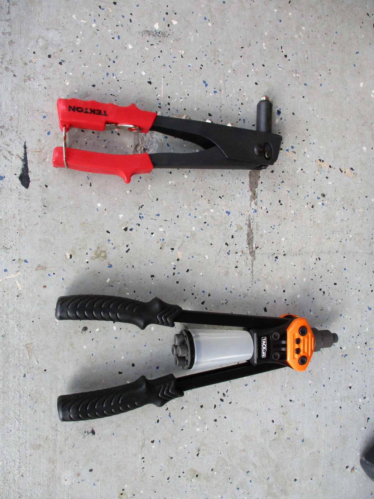
Here are the 2 riveters that we have. The hand tool I have had for some time and you can tell the amount of use that has been put on it. I bought the 2-handed one on the bottom thinking that it would be easier to use, but no such luck. It clamped on the nails and would not let go - even trying to hammer the nail through to the holding cup didn't work. I can't say that I recommend even trying with a similar 2-handed rivet gun - stick with the tried and true one that everyone seems to have.
")
OK will do - thanks!I have a similar riveter by the same company. You can try messing around with the screw on heads and it should work. Worked for me.
6/4/2018 Steering & Pedal Boxes #17 In Process
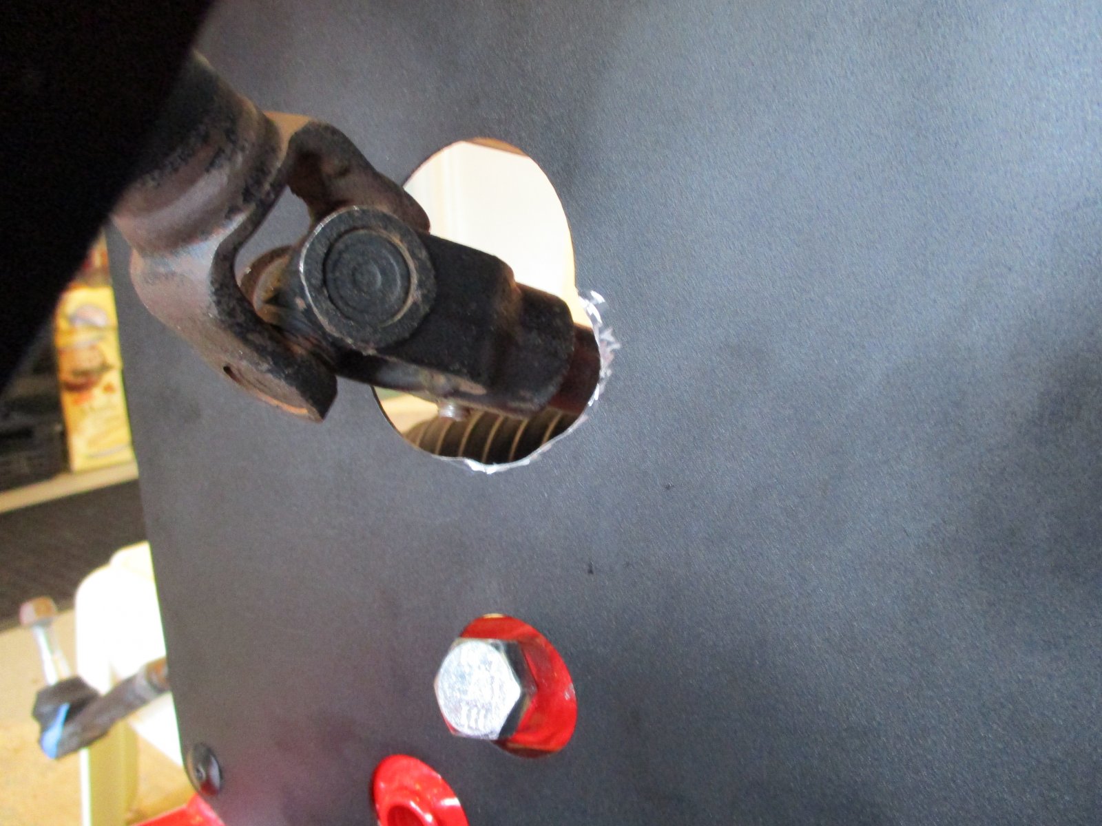
It looks like some more differences are turning up - in particular ours with a 2.4l Sport vs standard base model. The first of which is the firewall panel and steering link. It seems that the stem from the steering rack is not quite as long as the base (for whatever reason) and doesn't go through the metal plate as far. And thus when the steering link is added, it hits the sheet metal on the right hand side of the hole. We had to open up the hole by about 1/4" - see picture (this is the rough cut and will be smoothed out tomorrow).
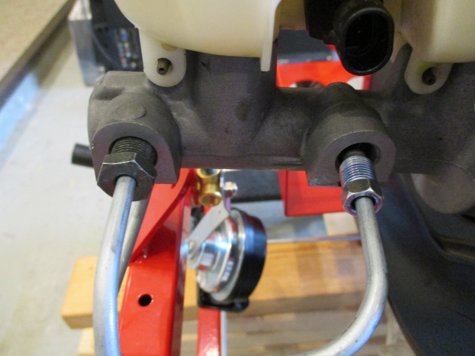
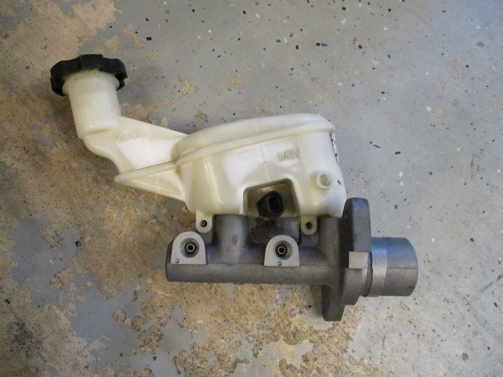
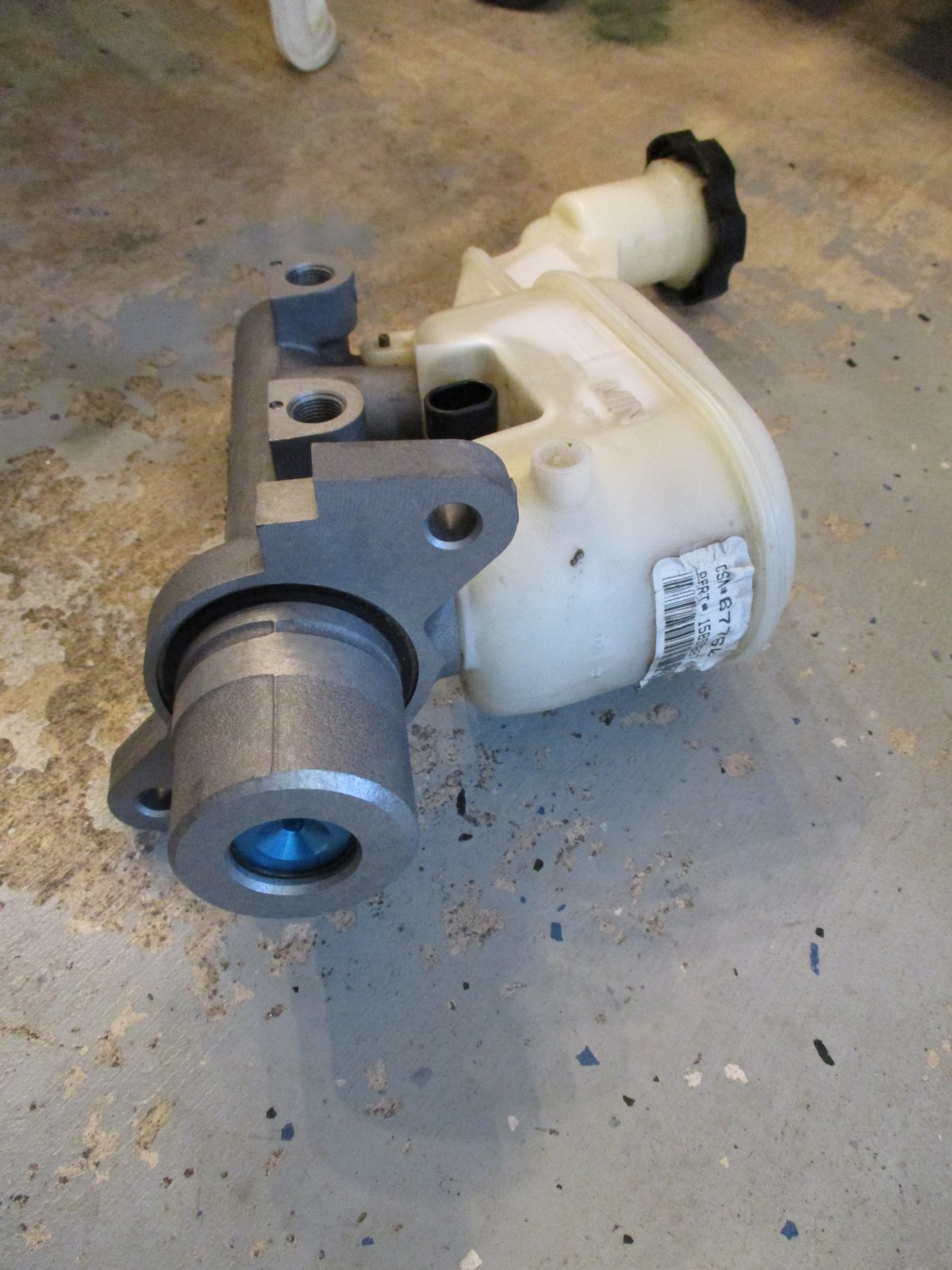
Next is on the brake reservoir. Ours does not have a bolt holding the tank on, but pins. They should be easy enough to take out and remove the tank later on as required. Also, the reservoir mounting stem is very different than in the video - it is much shorter and there is no aluminum spacer associated with the brake booster. Also, the rear brake line hole is much larger than the adapter - looks very much to be the same as the front.
Looks like we have a couple options and I'm looking for advice from folks who have been down this road already.
1. Go to junkyard and pull a master cylinder/reservoir from a base model. Does it mate only to the existing brake booster so get it too?
2. Keep going - would need to use an adapter for the rear line. I think this on has the right threads, correct?: https://smile.amazon.com/16-24-Female-Inverted-Adapter-10-13/dp/B06Y1CPL2G/ref=sr_1_8?ie=UTF8&qid=1528157213&sr=8-8&keywords=brake+line+adapter
3. Re-do the short brake line from cylinder to front Tee. Would need to get tubing, correct ends and bender kit. Certainly doable, but don't really want to store the kit for long term in the garage. Can I rent somewhere?
Thoughts? Suggestions?
Thanks!
It looks like some more differences are turning up - in particular ours with a 2.4l Sport vs standard base model. The first of which is the firewall panel and steering link. It seems that the stem from the steering rack is not quite as long as the base (for whatever reason) and doesn't go through the metal plate as far. And thus when the steering link is added, it hits the sheet metal on the right hand side of the hole. We had to open up the hole by about 1/4" - see picture (this is the rough cut and will be smoothed out tomorrow).
Next is on the brake reservoir. Ours does not have a bolt holding the tank on, but pins. They should be easy enough to take out and remove the tank later on as required. Also, the reservoir mounting stem is very different than in the video - it is much shorter and there is no aluminum spacer associated with the brake booster. Also, the rear brake line hole is much larger than the adapter - looks very much to be the same as the front.
Looks like we have a couple options and I'm looking for advice from folks who have been down this road already.
1. Go to junkyard and pull a master cylinder/reservoir from a base model. Does it mate only to the existing brake booster so get it too?
2. Keep going - would need to use an adapter for the rear line. I think this on has the right threads, correct?: https://smile.amazon.com/16-24-Female-Inverted-Adapter-10-13/dp/B06Y1CPL2G/ref=sr_1_8?ie=UTF8&qid=1528157213&sr=8-8&keywords=brake+line+adapter
3. Re-do the short brake line from cylinder to front Tee. Would need to get tubing, correct ends and bender kit. Certainly doable, but don't really want to store the kit for long term in the garage. Can I rent somewhere?
Thoughts? Suggestions?
Thanks!
ctuinstra
Goblin Guru
1) The pins in the reservoir are normal. We had pins also. Just carefully push them out one side and pull it straight up. You will bolt it done to the brake pedal box with bolts and spacers.
2) The adaptor, if it's correct I don't know for sure, would be a very quick and easy way to go.
3) Cut off the flare and change out the fitting and re-flare it. You would have to buy the flaring tool and the correct fitting.
2) The adaptor, if it's correct I don't know for sure, would be a very quick and easy way to go.
3) Cut off the flare and change out the fitting and re-flare it. You would have to buy the flaring tool and the correct fitting.
Option 4. Have Adam send you one of the SS/TC brake lines that has the larger fitting.Looks like we have a couple options and I'm looking for advice from folks who have been down this road already.
1. Go to junkyard and pull a master cylinder/reservoir from a base model. Does it mate only to the existing brake booster so get it too?
2. Keep going - would need to use an adapter for the rear line. I think this on has the right threads, correct?: https://smile.amazon.com/16-24-Female-Inverted-Adapter-10-13/dp/B06Y1CPL2G/ref=sr_1_8?ie=UTF8&qid=1528157213&sr=8-8&keywords=brake+line+adapter
3. Re-do the short brake line from cylinder to front Tee. Would need to get tubing, correct ends and bender kit. Certainly doable, but don't really want to store the kit for long term in the garage. Can I rent somewhere?
I'll send you one tomorrow and I'll take note that the 2.4 uses the same line as the SS/TC. Thanks for being the guinea pig on the 2.4 liter build.
theeulogy
Well-Known Member
I had to do the same thing also.And we had to also do the same thing for the steering shaft.
Briann1177
Goblin Guru
Ditto with filing out the sheet metal for the steering shaft. Not sure why that cut out can't be changed to begin with. At least it's an easy fix.
6/7/2018 Powertrain & Fuse Box Video #20 In process - #'s 17-19 Complete
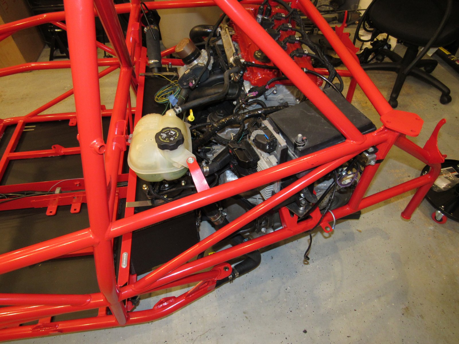
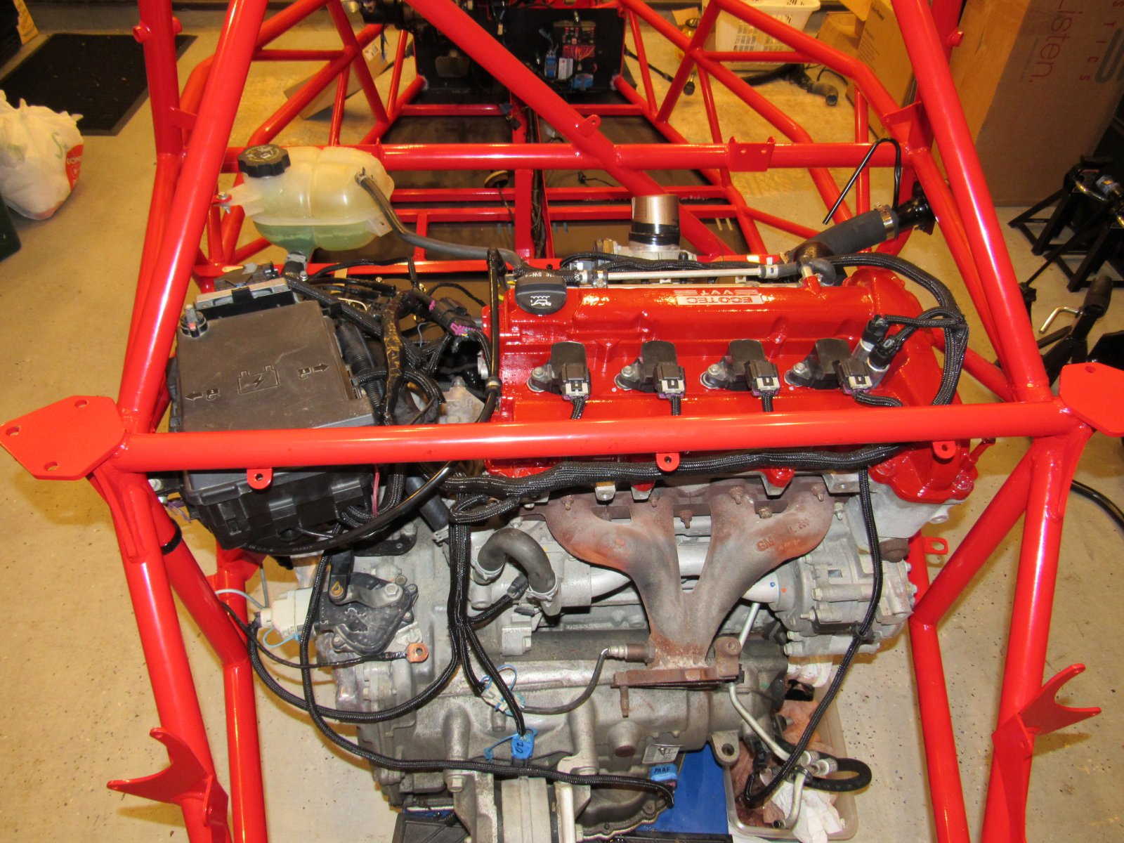
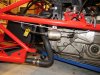
Wow! In a couple of days we have made it to the point of having the engine just installed and starting to try and figure out the fuse box mounting plan. We have been extra paranoid on grounding and have really gone out of our way to try and make as many connections as possible by grinding off paint and powder coat to various surfaces that meet. i.e. bottom side of engine mounts and top of engine/transmission, where the steering arm extension meets the pedal box, pedal box to frame, ground lug to pedal box, ground lug to tunnel (even had to drill an extra hole for this one because wires were just too short). Also, checking continuity across multiple grounds during the process has helped. I can check from engine block to bolts holding dash gauges and everywhere in between and get a tone immediately - hopefully this will help prevent any electrical issues further down the line!
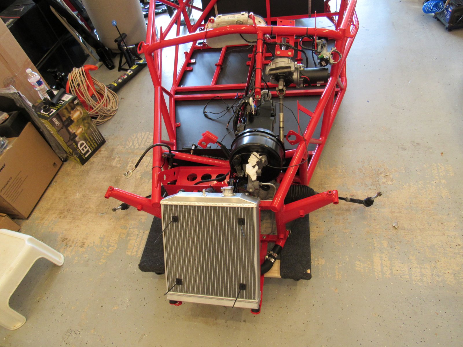
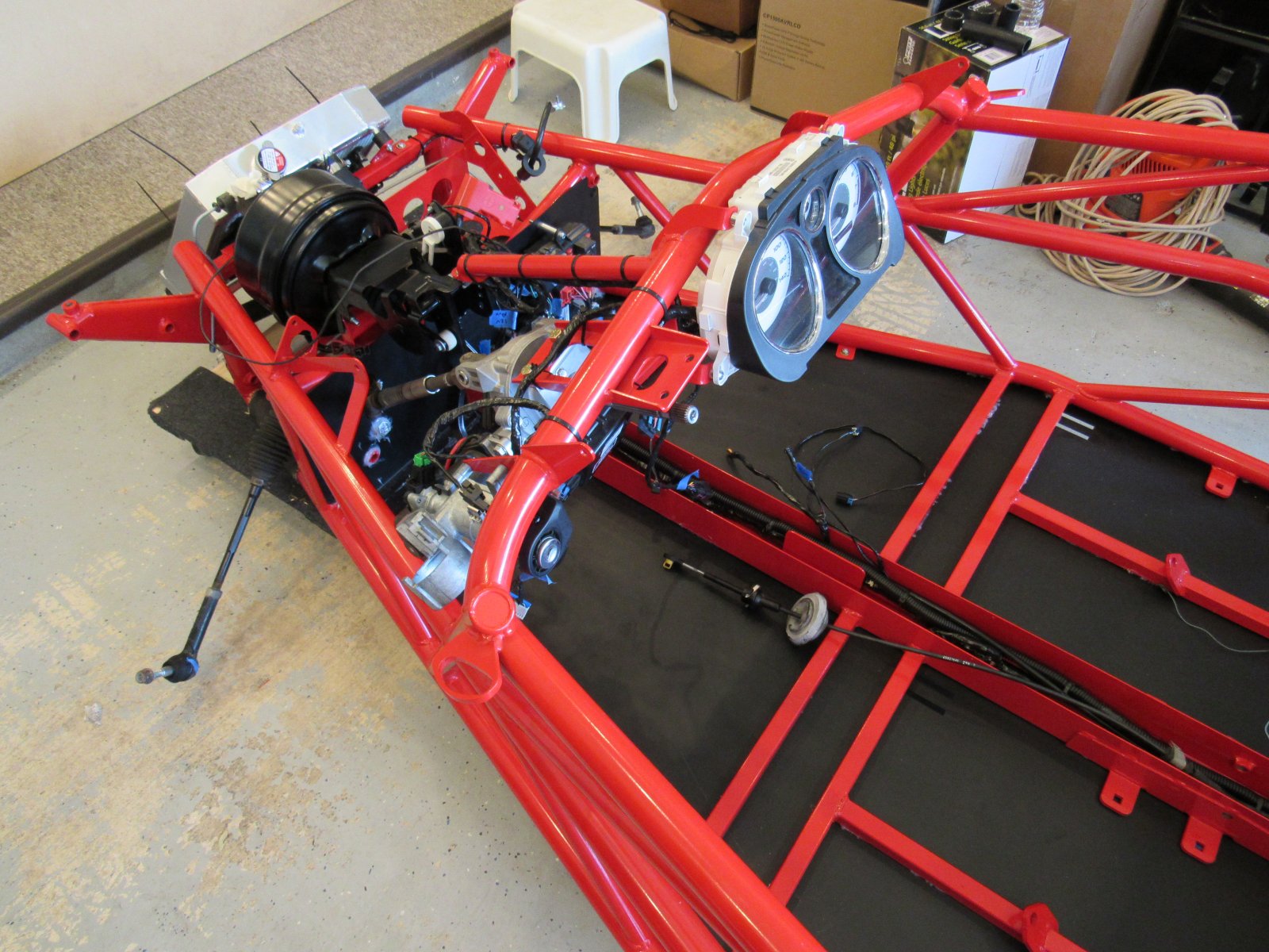
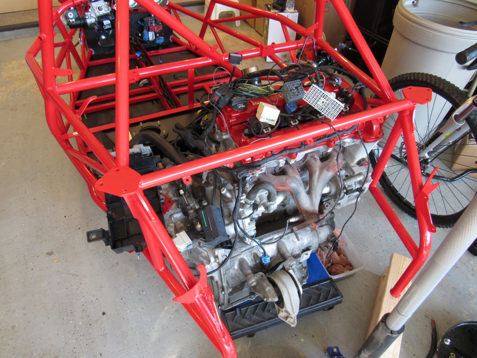
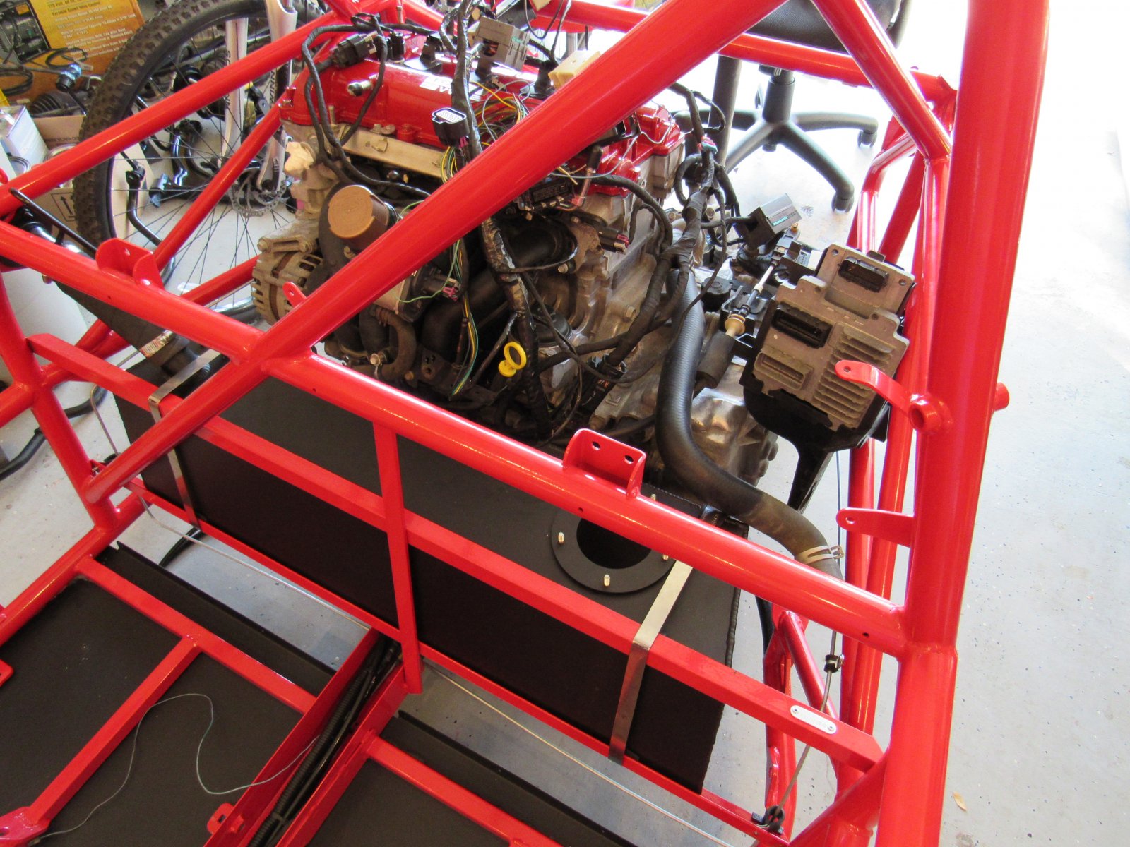
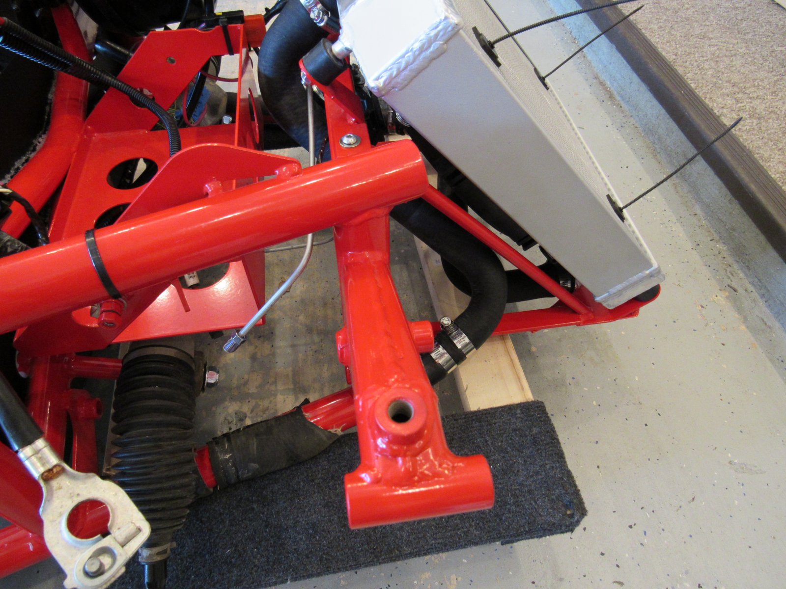
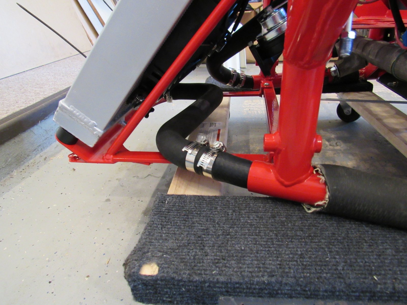
Also, we decided to have the water pump pull from the lowest point and crossed the radiator. It turned out rather nice with a 2nd 71796 radiator hose!
Wow! In a couple of days we have made it to the point of having the engine just installed and starting to try and figure out the fuse box mounting plan. We have been extra paranoid on grounding and have really gone out of our way to try and make as many connections as possible by grinding off paint and powder coat to various surfaces that meet. i.e. bottom side of engine mounts and top of engine/transmission, where the steering arm extension meets the pedal box, pedal box to frame, ground lug to pedal box, ground lug to tunnel (even had to drill an extra hole for this one because wires were just too short). Also, checking continuity across multiple grounds during the process has helped. I can check from engine block to bolts holding dash gauges and everywhere in between and get a tone immediately - hopefully this will help prevent any electrical issues further down the line!
Also, we decided to have the water pump pull from the lowest point and crossed the radiator. It turned out rather nice with a 2nd 71796 radiator hose!
6/26/2018 Powertrain & Fuse Box Video #20 Mostly Complete
A couple of questions:
1. Fuel lines - these are bent and held in place. Any concern about breaking? I have read other places in these build logs where they are easy to break, especially at the mount to the fuel pump.
2. Fuel line out of fuel filter to engine: I tried several times to seat that metal piece into fuel filter, but that is all the far in that I can get it. Not nearly as far as in the video, so is that normal by chance? Or do I need to look at a new filter?
(BTW putting those ends on the fuel line was almost as difficult as pulling the cooling lines through the frame! Ended up using a heat gun to help - after some experimentation, only use about 3 seconds of heat gun as beyond that time makes it very easy to melt and kink the line. Yes literally count to 3-one-thousand and take the heat off, start twisting in the fuel elbow then tap the rest of the way in with a mallet)
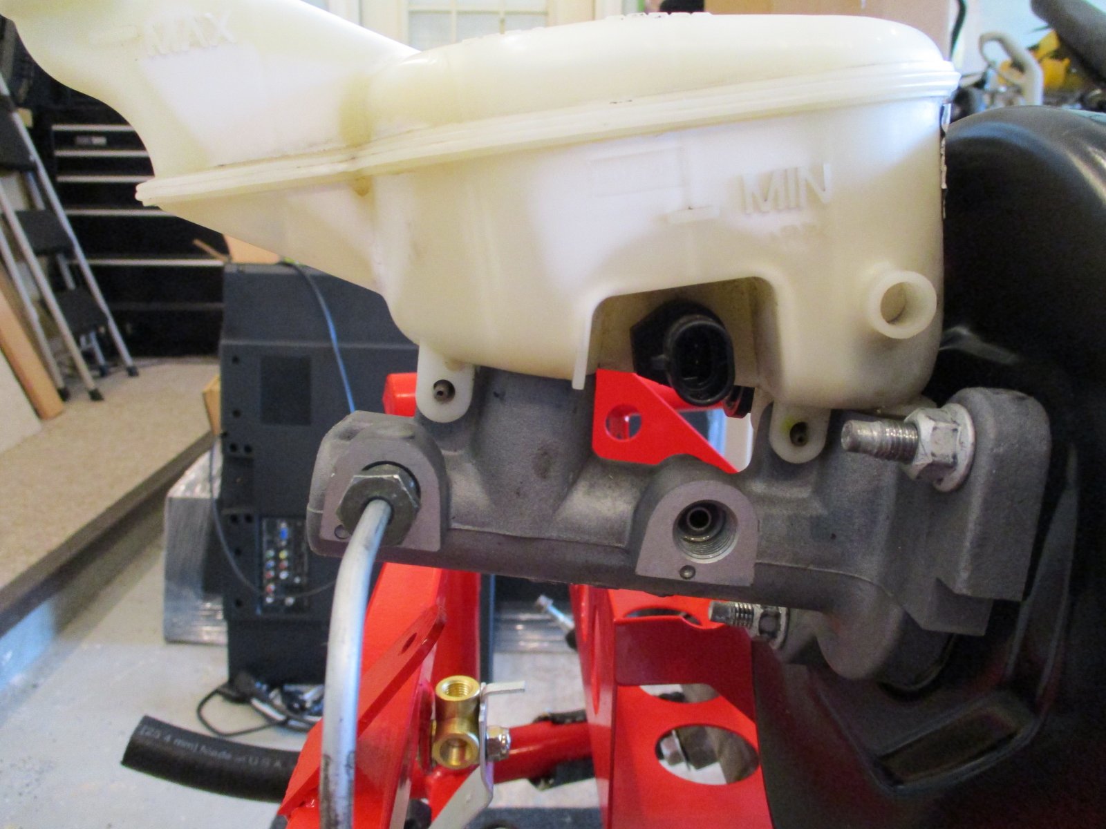
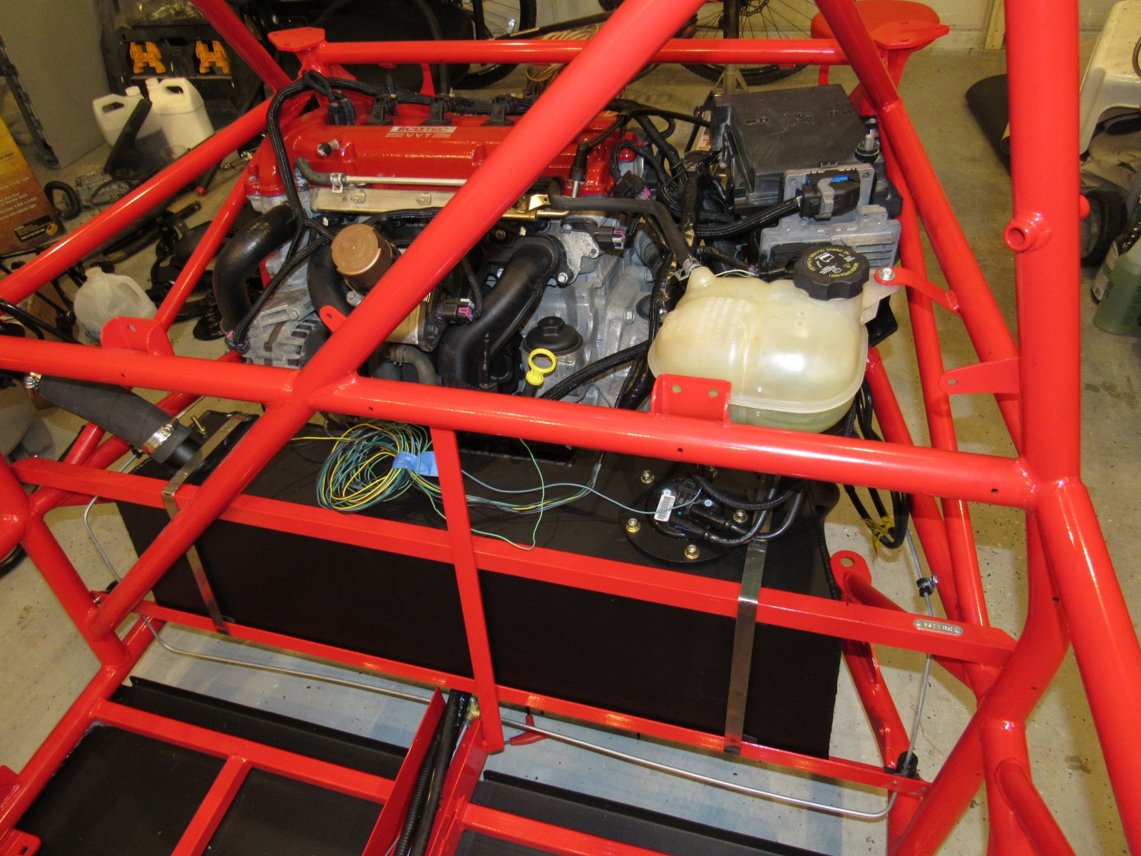
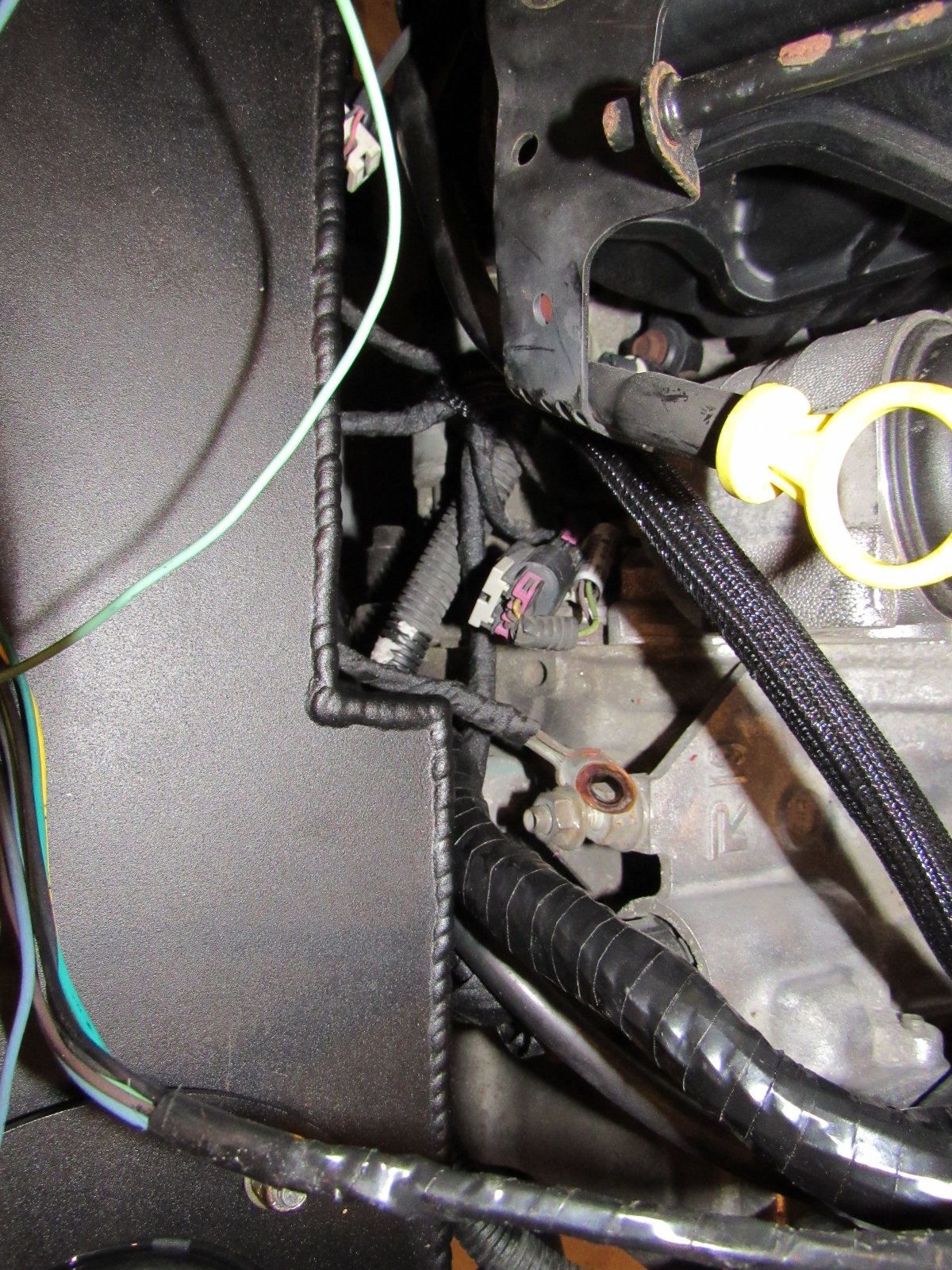
Also on grounds. We have 2 grounds not hooked up yet. The first is the ground from the main harness - I think it goes on the front of the transmission as in this photo. Correct? If not, where?
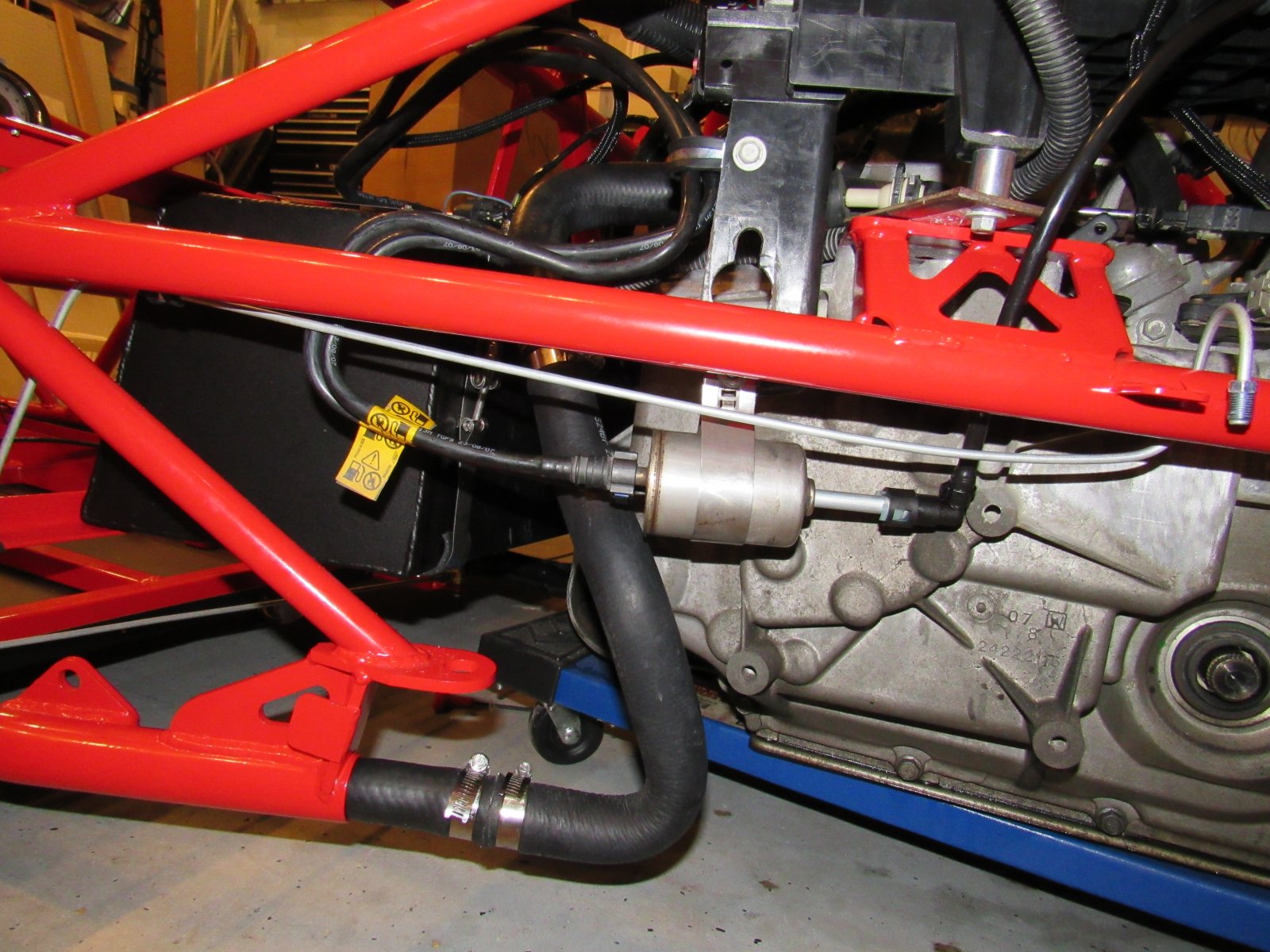
The second ground is the one from the main harness near the fuse box. I thought I saw a picture or description somewhere saying where to put it but can't seem to find it now. Does it go here on the driver side near the rear of the transmission?
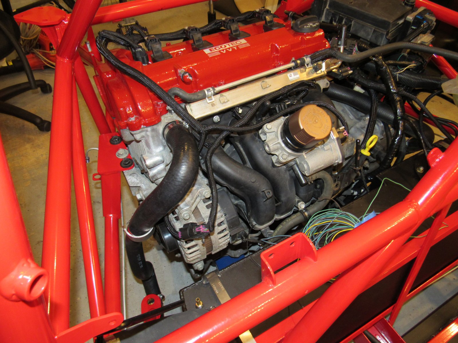
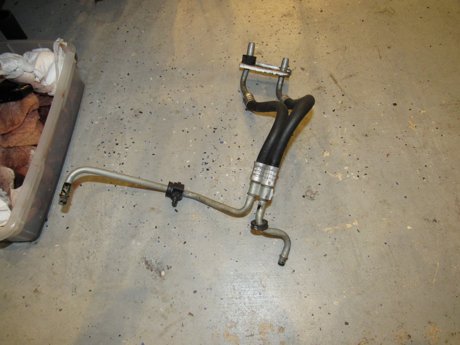
Lastly, a question on the transmission cooling lines. The video shows reconnecting the adapter below to the front of the engine, but unless we missed it, there are still open ends that used to connect to the radiator. Don't we have to close this loop somehow?
A couple of questions:
1. Fuel lines - these are bent and held in place. Any concern about breaking? I have read other places in these build logs where they are easy to break, especially at the mount to the fuel pump.
2. Fuel line out of fuel filter to engine: I tried several times to seat that metal piece into fuel filter, but that is all the far in that I can get it. Not nearly as far as in the video, so is that normal by chance? Or do I need to look at a new filter?
(BTW putting those ends on the fuel line was almost as difficult as pulling the cooling lines through the frame! Ended up using a heat gun to help - after some experimentation, only use about 3 seconds of heat gun as beyond that time makes it very easy to melt and kink the line. Yes literally count to 3-one-thousand and take the heat off, start twisting in the fuel elbow then tap the rest of the way in with a mallet)
Also on grounds. We have 2 grounds not hooked up yet. The first is the ground from the main harness - I think it goes on the front of the transmission as in this photo. Correct? If not, where?
The second ground is the one from the main harness near the fuse box. I thought I saw a picture or description somewhere saying where to put it but can't seem to find it now. Does it go here on the driver side near the rear of the transmission?
Lastly, a question on the transmission cooling lines. The video shows reconnecting the adapter below to the front of the engine, but unless we missed it, there are still open ends that used to connect to the radiator. Don't we have to close this loop somehow?
Attachments
-
 335.7 KB Views: 381
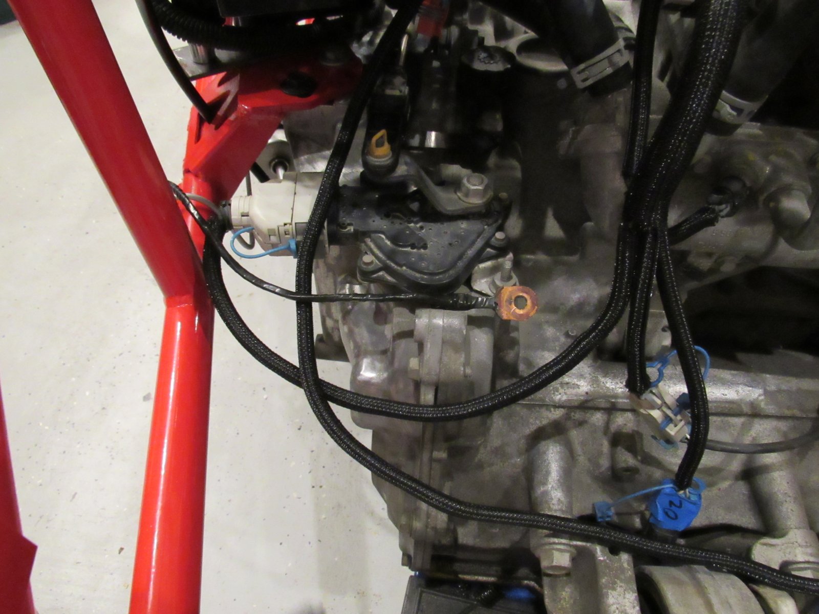
So we have this thick short ground cable (it's about 18" - hard to tell length in photo below) that I can't remember where it was when we pulled it off. I thought I had pictures of where everything was prior to removal but ???....
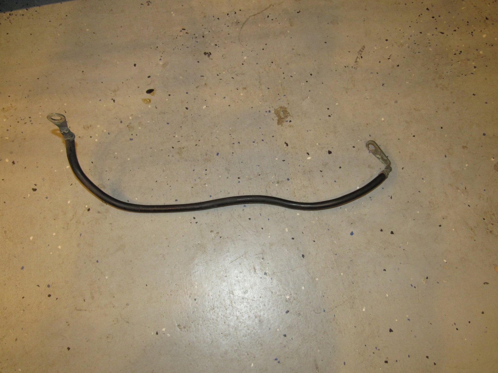
If looks like it goes from the engine to the frame per Tony @ http://www.dfkitcar.com/forum/index.php?threads/tonys-city-goblin-2010-ss-tc.232/post-8301
I see where it connects to the frame, but the other (engine) end does not look like our engine. Where should we connect this to the engine? A nagging memory in the back of my head seems to say starter but I'm not sure. Maybe the front transmission bolt like ground question picture in the prior post?
Thanks!
JSATX
Goblin Guru
1) I recommend cutting the hard factory line off the nipple at the pump. Then replacing with flexible fuel injection hose and an injection rated clamp. It opens up many more routing options.6/26/2018 Powertrain & Fuse Box Video #20 Mostly Complete
View attachment 4302
View attachment 4304
View attachment 4307
View attachment 4308
A couple of questions:
1. Fuel lines - these are bent and held in place. Any concern about breaking? I have read other places in these build logs where they are easy to break, especially at the mount to the fuel pump.
2. Fuel line out of fuel filter to engine: I tried several times to seat that metal piece into fuel filter, but that is all the far in that I can get it. Not nearly as far as in the video, so is that normal by chance? Or do I need to look at a new filter?
(BTW putting those ends on the fuel line was almost as difficult as pulling the cooling lines through the frame! Ended up using a heat gun to help - after some experimentation, only use about 3 seconds of heat gun as beyond that time makes it very easy to melt and kink the line. Yes literally count to 3-one-thousand and take the heat off, start twisting in the fuel elbow then tap the rest of the way in with a mallet)
View attachment 4310
Also on grounds. We have 2 grounds not hooked up yet. The first is the ground from the main harness - I think it goes on the front of the transmission as in this photo. Correct? If not, where?
View attachment 4306
The second ground is the one from the main harness near the fuse box. I thought I saw a picture or description somewhere saying where to put it but can't seem to find it now. Does it go here on the driver side near the rear of the transmission?
View attachment 4303
Lastly, a question on the transmission cooling lines. The video shows reconnecting the adapter below to the front of the engine, but unless we missed it, there are still open ends that used to connect to the radiator. Don't we have to close this loop somehow?
View attachment 4305
2) chuck the fuel filter adapter tube into a drill and polish with 600grit sand paper for just a couple seconds. Then a little oil and light pressure with a vice and it’ll press right in.
Briann1177
Goblin Guru
If you ground off the powder coat where the engine contacts the frame, you really don't need the ground wire that connects to the frame. Its up to you. I'm not using mine as it just gets in the way and is extra clutter I'd rather not have.