Brian's City Goblin-06/Crate MotorTC #61

Brian74

Goblin Guru
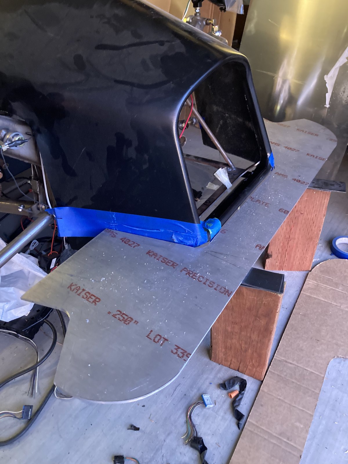
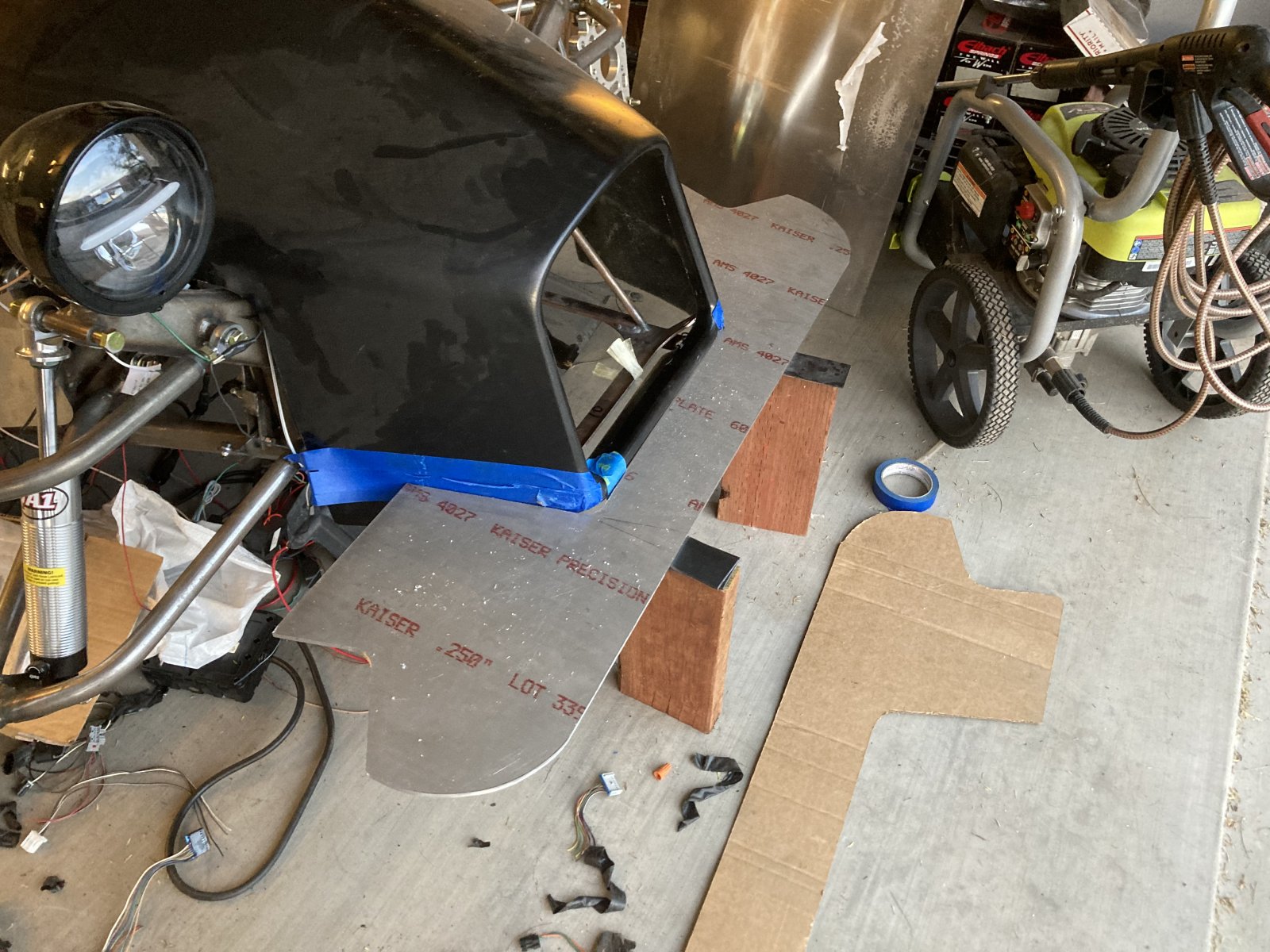
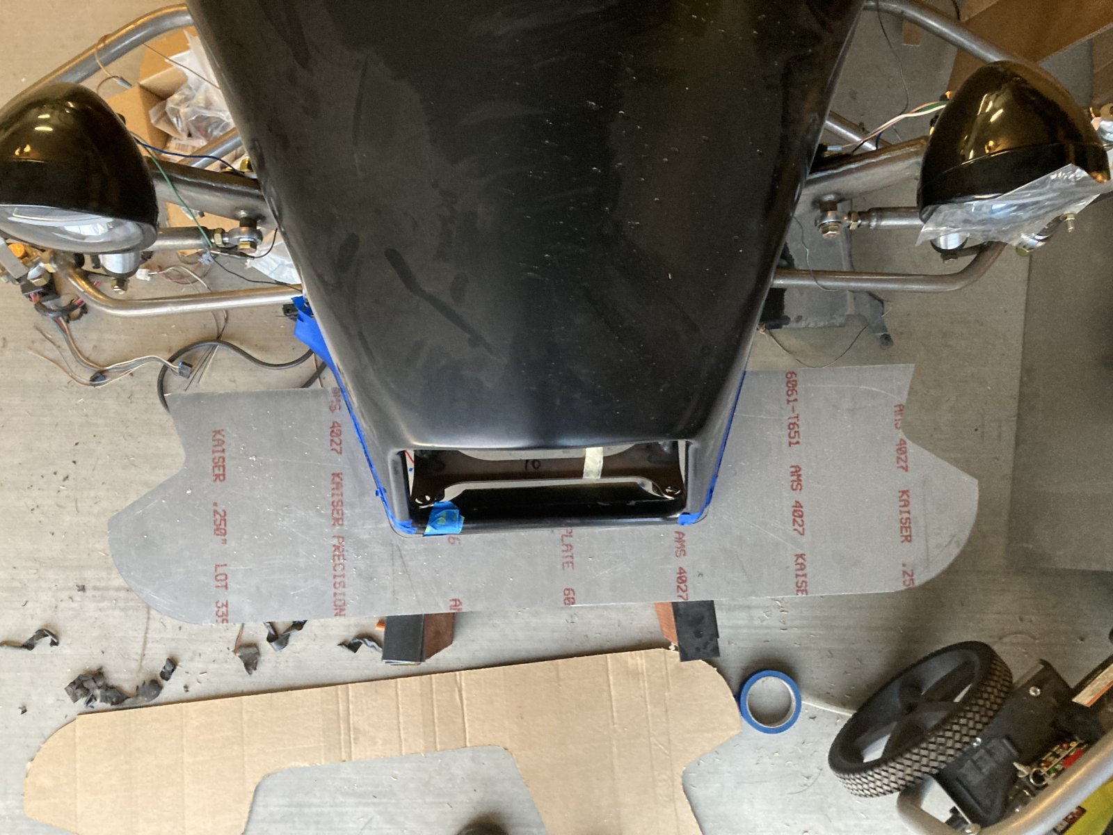
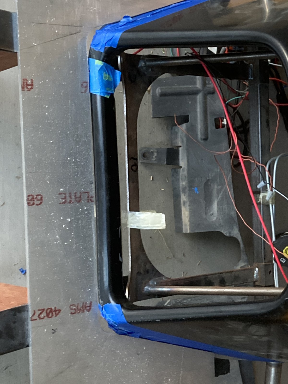
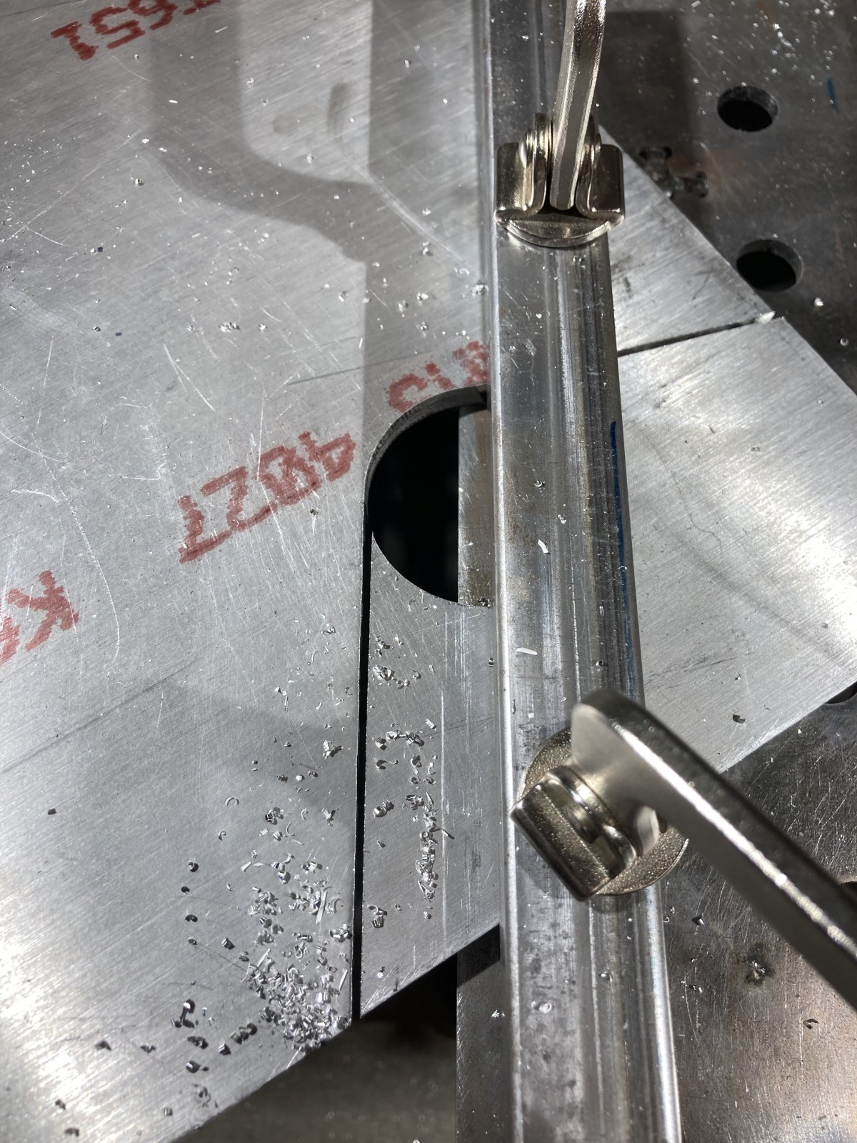
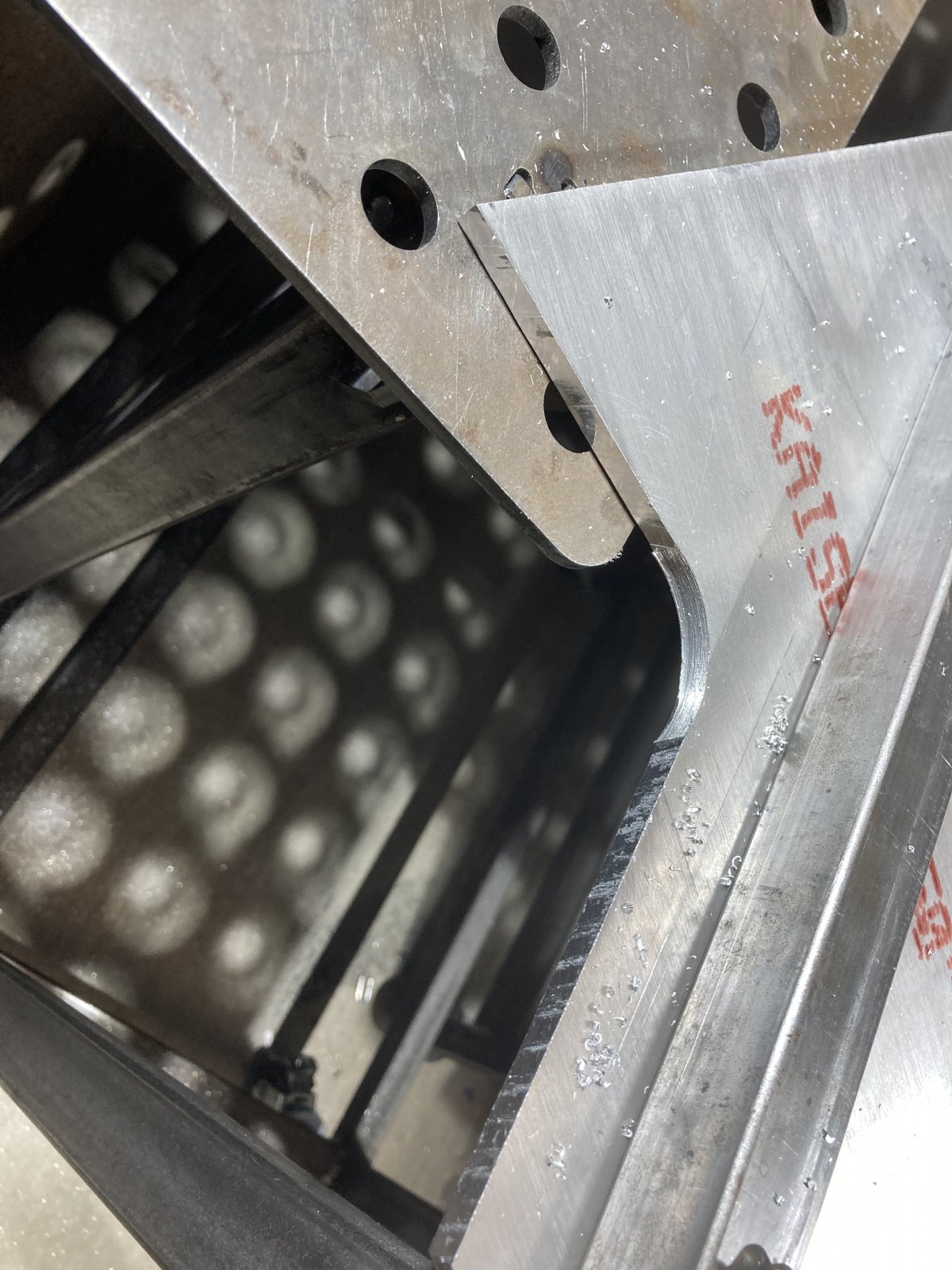
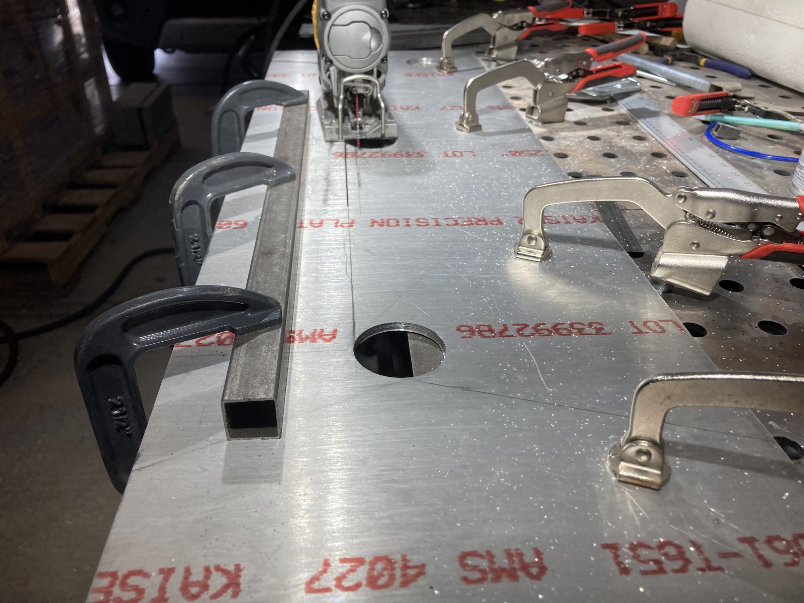
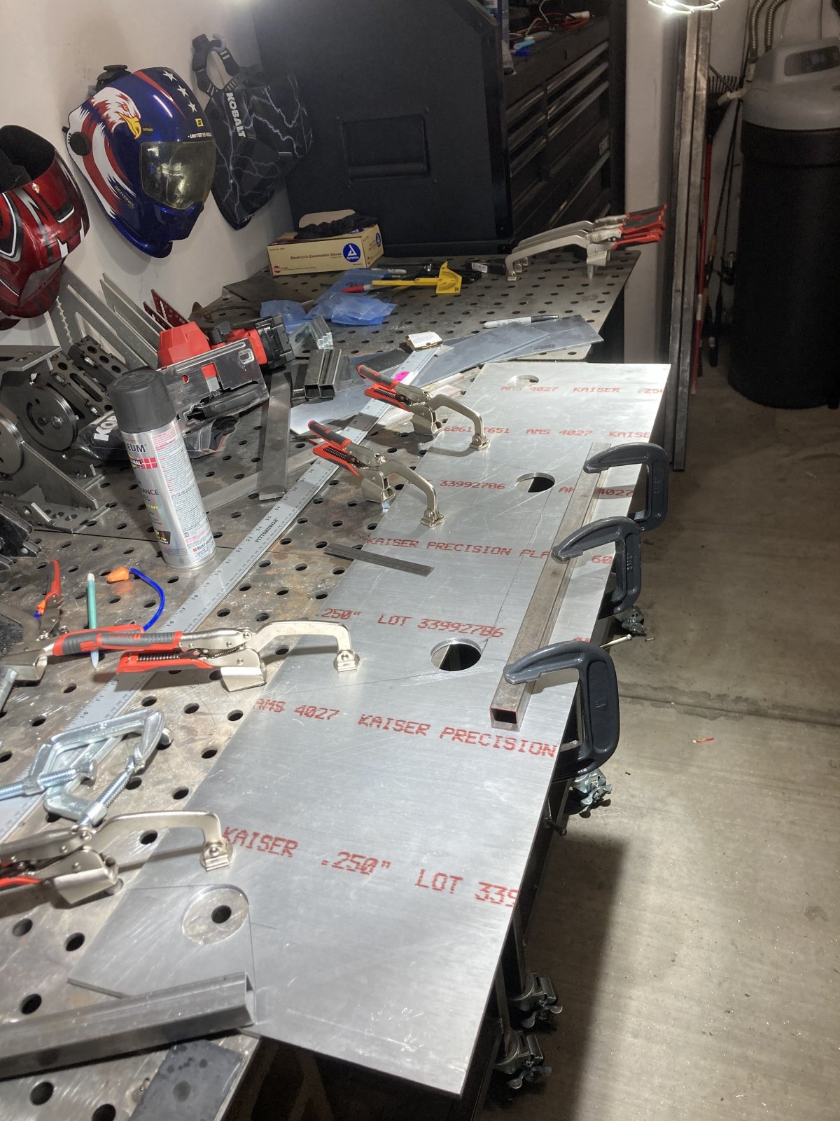
Spoiler is cut out. Ended up weighing 8.8 lbs. I ordered a press brake to do the bends, which wont be here for 2 more weeks. I still need to run a 90 degree orbital drum around the perimeter and round out the sharp edges. I will probably do 1/8” radius cuts on the leading & trailing edges.

I thought about 3D printing some abs lower trailing edge airfoils and side stabilizers; as my big printer could easily handle it… Not sure yet.

487E3950-FF76-4793-9B62-2C353053C334.jpeg
FC2476FF-BEA8-44F2-96F9-DDA4EAC78429.jpeg
F15CE37C-5DE9-4F89-B046-73D877EA987C.jpeg
1B15126A-3275-4527-B742-B0143F60F6AD.jpeg
73938E51-FB37-4F5D-964A-75C39632673D.jpeg
D0313A04-F726-4117-BDA3-5AD671854C77.jpeg
8CDA2E25-2D3E-4F5A-B62B-58545D3DE8C5.jpeg
BE71EDEE-FD05-4970-A9CD-296F6A044564.jpeg
 

Lonny

Administrator
Staff member
I have a feeling you may have trouble bending that material. With a T6 heat treat it will probably crack.

Try bending a scrap piece in a vise with a hammer.

It will also take a very serious press brake to bend it.

You can heat along the bend line with a torch and then allow it to cool to remove some of the heat treatment.

If it doesn't work out you may want to try .125 thickness and bend it over a piece of tubing to give it a radius bend. I think .125 would be stiff enough once you put a bend in it.
 

Brian74

Goblin Guru
I have a feeling you may have trouble bending that material. With a T6 heat treat it will probably crack.

Try bending a scrap piece in a vise with a hammer.

It will also take a very serious press brake to bend it.

You can heat along the bend line with a torch and then allow it to cool to remove some of the heat treatment.

If it doesn't work out you may want to try .125 thickness and bend it over a piece of tubing to give it a radius bend. I think .125 would be stiff enough once you put a bend in it.
I’ve got a fair amount of scrap to practice with. I was planning to preheat it to drop some of the temper. I’m only looking for about 12-15 degrees and more of a radius than sharp bend. The press brake I’m getting is rated at 20 tons. Since I have good dimensions at this point, I’ll have no problem going to thinner material if need be.
 
Last edited:

Lonny

Administrator
Staff member
20 ton, that should do it.

It would be neat if you could easily adjust the angle of attack to get the best down force.
 

Brian74

Goblin Guru
You weren’t kidding Lonny. I just went out to the shop and beat the living **** out of a 4” piece using a 10 lb hammer. I may need build some lower press jigs up spaced out with radius tubing. I’ve gotten so many different opinions from different people so far.
 

Brian74

Goblin Guru
20 ton, that should do it.

It would be neat if you could easily adjust the angle of attack to get the best down force.
If I had a wind tunnel, lol. I am debating on installing 200 lb linear actuators on the trailing ends just to be able to change the AOA on the fly and find a downforce angle that seems to work the best.

I designed the mounting configuration based on this. Once the most efficient AOA is established, then the actuators come off and get replaced with turnbuckles.
 
Last edited:

Brian74

Goblin Guru
One of my other ideas… I guess If you are a serious road racer at different tracks with various entry speed corners, the linear actuators could have preset angles, based on speed, and program the spoiler AOA angle/downforce based on that speed. That would not be tough to design using a GPS speed sensor that provides a variable analog control signal to the actuators.
 

Brian74

Goblin Guru
Continuing on with my spoiler design. I have been on Fusion360 for the past few days struggling through it. I played with component assembly modules a bit, and redesigned the front spoiler design clearances slightly using a carefully measured steering axis mockup with 245/50 16 tires.

Today I started messing with airfoil design. At some point it all just clicked and finally made sense. I literally had a coming to God revelation once I realized the fundamental design theory behind CAD.

After that, I quickly designed a lower aft airfoil section for the spoiler to reduce some of the drag coefficient at the trailing edge. I can easily print this piece and bond/mount it to the spoiler.

I really need to get my plasma table ordered.

D5C1C218-7346-44A0-86A2-7C608426FCA1.jpeg
F76CA8DF-6309-4FB9-B83B-BD6EE92AB4B5.jpeg
EB966C8C-3B31-491E-952E-F20B1B1DE8B1.jpeg
AB46DDE3-F3F6-481C-BCBF-5B07A31B935B.jpeg
6B1841EB-B7A5-4977-9698-0074319BDC2A.jpeg
E09B48B9-CFD9-47E2-98C3-2E808F0677A1.jpeg
488F1BA5-9B3F-4540-97F0-0A277E13F74E.jpeg
9134ADF5-780F-4D85-9A20-D70E0ED7D2E6.jpeg
3BD368FB-58EA-49EC-BF97-3CDA03EE8979.png
52FF1293-E96F-46C6-A7D2-03F1F370E43B.png
4F7F5494-9BAE-4C66-B101-21227802D685.png
 
Last edited:

Torchandregdoc

Goblin Guru
I'm 55. I'm a fairly quick learner. I was given an Autocad subscription and I can't figure out how to do a plan of my backyard. It is completely Greek to me. My son plays with it for 10 minutes and has everything sketched out. Like I said, you kids suck.
 

Desert Sasqwatch

Goblin Guru
Continuing on with my spoiler design. I have been on Fusion360 for the past few days struggling through it. I played with component assembly modules a bit, and redesigned the front spoiler design clearances slightly using a carefully measured steering axis mockup with 245/50 16 tires.

Today I started messing with airfoil design. At some point it all just clicked and finally made sense. I literally had a coming to God revelation once I realized the fundamental design theory behind CAD.

After that, I quickly designed a lower aft airfoil section for the spoiler to reduce some of the drag coefficient at the trailing edge. I can easily print this piece and bond/mount it to the spoiler.

I really need to get my plasma table ordered.

View attachment 29827View attachment 29828View attachment 29829View attachment 29830View attachment 29831View attachment 29832View attachment 29833View attachment 29834View attachment 29835View attachment 29836View attachment 29837
Brian,
From the pics in your post it looks like the airfoil will be on top of the plate? Or is this just for design purposes? The airfoil must be on the bottom of the splitter plate to create 'lift' in the downward direction to create downforce. Putting the airfoil on top will create lift upward, defeating the purpose of the splitter. Didn't want this to get to far and then realize the new splitter wing is oriented the wrong way to create downforce. :)
 

Brian74

Goblin Guru
Brian,
From the pics in your post it looks like the airfoil will be on top of the plate? Or is this just for design purposes? The airfoil must be on the bottom of the splitter plate to create 'lift' in the downward direction to create downforce. Putting the airfoil on top will create lift upward, defeating the purpose of the splitter. Didn't want this to get to far and then realize the new splitter wing is oriented the wrong way to create downforce. :)
The airfoil is indeed on the bottom. The pics are more to show the design shape than anything.
 

Brian74

Goblin Guru
I got my new press brake set up. Threw in a 12” piece of 1/4” thick 6061 T-6 and cranked it down. It bent effortlessly; I’m guessing around 5-6 tons. This is great! I will cut out the prototype now and start working through the mounting bracket design.

4E9782A7-E506-4C4B-AA48-FB25C334B931.jpeg
23BCB1B1-4646-4C3A-851C-78781D5C5FE8.jpeg
74E06386-B150-4672-9B85-1B9B42ED3E9C.png
 

Brian74

Goblin Guru
Your garage is starting to look like the Roush / M Power / Hennessy aftermarket version for the DF Goblin!!!!!……. ;)
It’s certainly come a long way. I gotta be all strategic at this point, as I’m running out of room. We need to stay here for at least 5 more years until I can retire.
 

Brian74

Goblin Guru
I decided to start a little side project today. I want to try more challenging CAD projects as I want to become proficient. I also love mind-bending projects.

I decided to try and reproduce a CAD model of the front cowling. I think having a good cowling CAD model will help me get my final spoiler angles just right and could be good for future projects. After some brainstorming, I hit the hardware store and picked up some laser measuring tools.

I oriented and jigged up the cowling on an appropriate XY plane and drew out section lines to plot the vertical plane measurements down the Y axis. I then created numerous data points along the 9 vertical planes, and took the measurements.

I still need to flip the cowling 90 degrees and shoot some measurements in the X axis plane.

I will throw this data into the CAD, and then build out the planes using fixed point splines. It wont be perfect, but it will be pretty **** close.

A626D839-B817-4F42-87C5-B152926C9374.jpeg
D84393FF-DCCA-4B0E-A04B-31DCEEB0991B.jpeg
4EF089A2-EF0A-4CD6-9C06-46C461C34540.jpeg
BFF91EED-4ADB-45FD-ADA4-93D8CE88E96C.jpeg
 
Top