Brian's City Goblin-06/Crate MotorTC #61
- Thread starter Brian74
- Start date
Brian74
Goblin Guru
Did some more work on the cowling. Realized most of those measurements I took really weren’t even needed, although it is good to see the profile and see how adjusting the mesh affects the layers. Nothing easy about this, but with what I’ve learned from this so far, designing stuff will be way easier now.
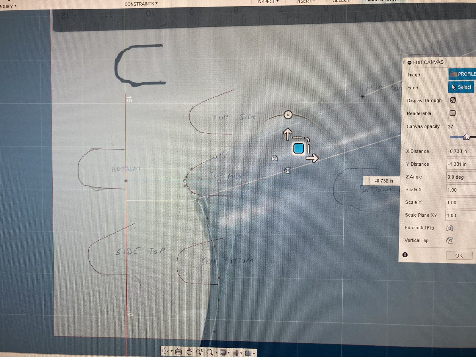
I also learned a cool little trick today with superimposing scaled 2-D images on to reference planes to create planar templates. That will come in super helpful later on.
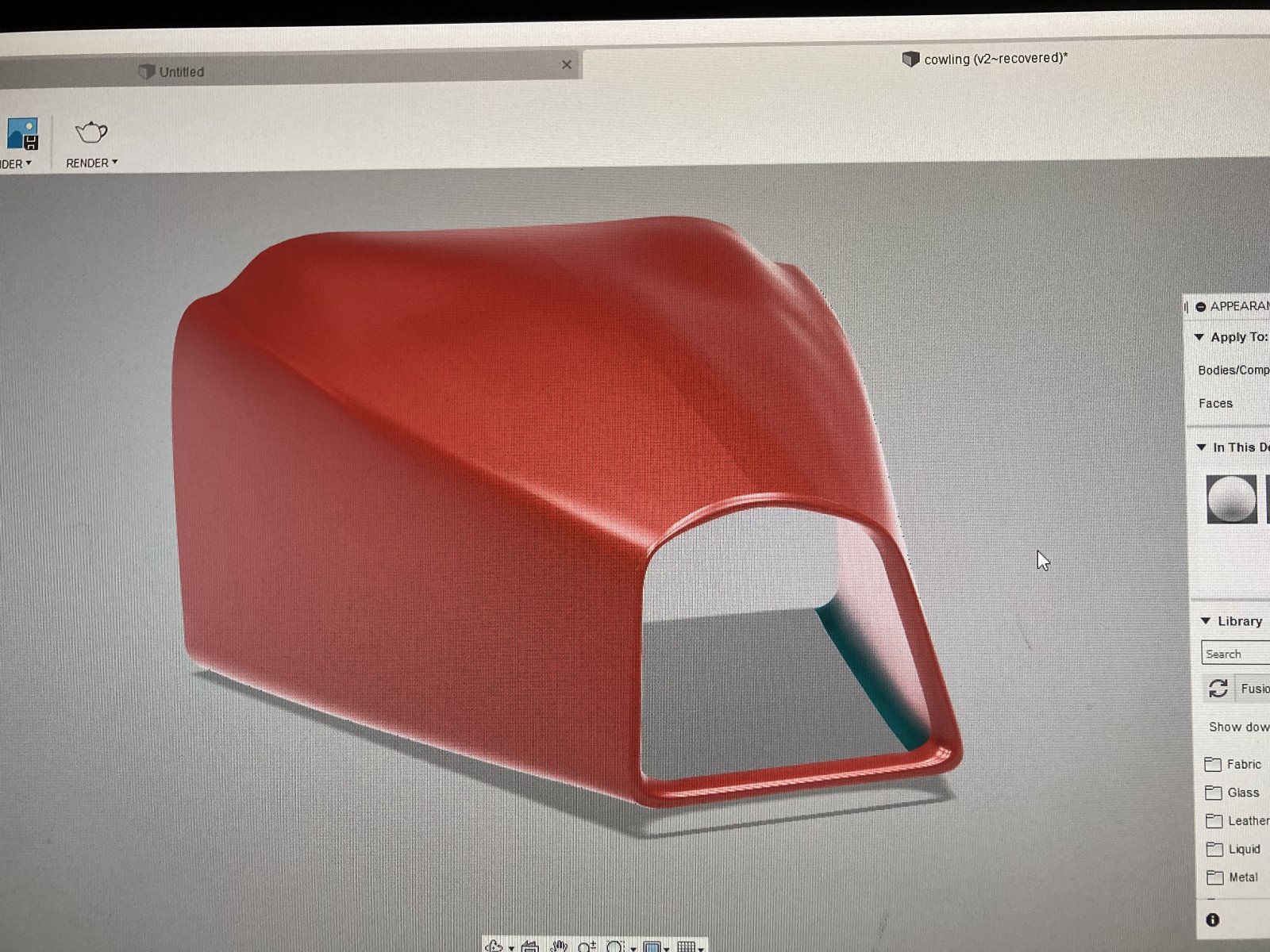
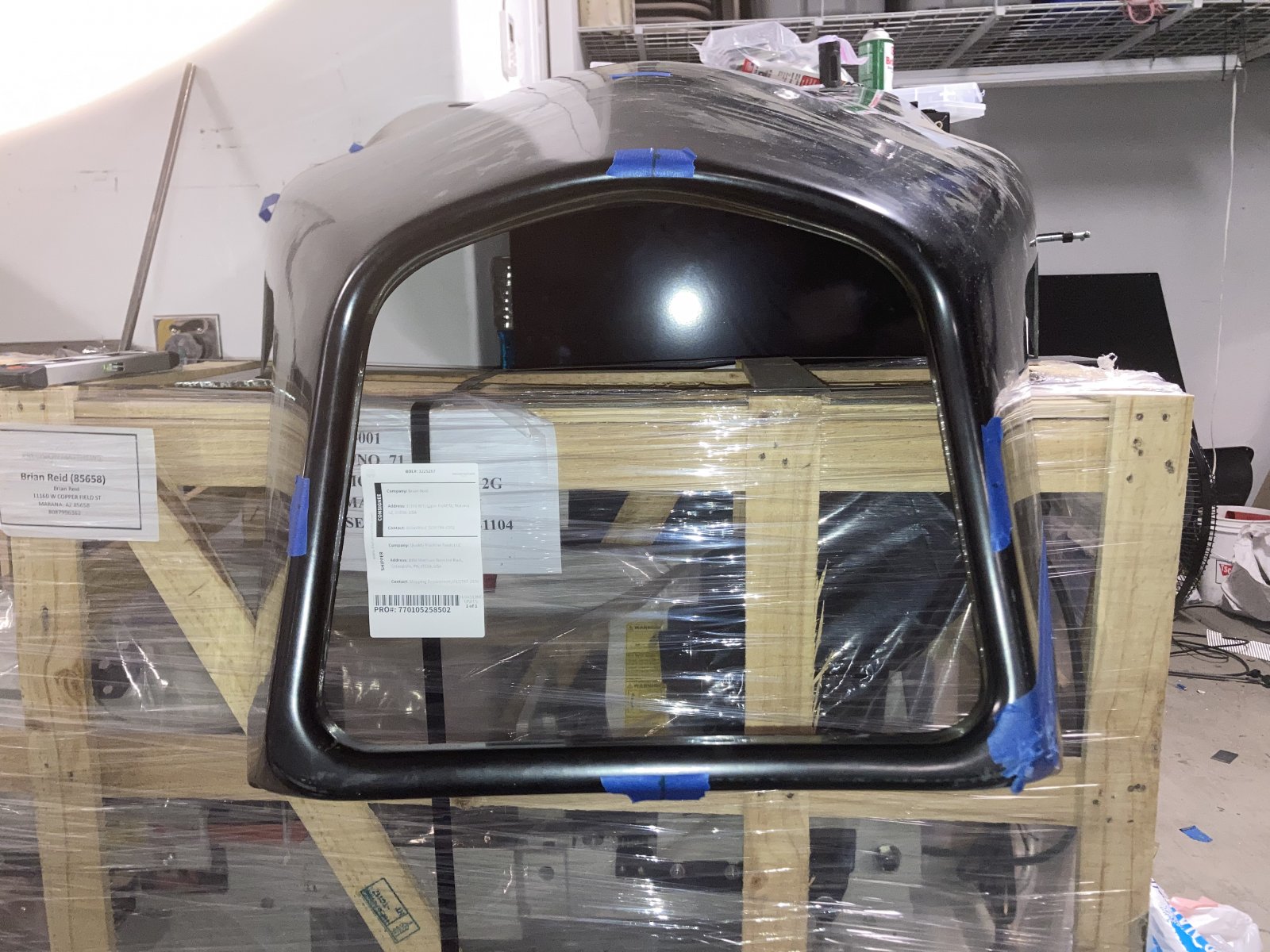
I also learned a cool little trick today with superimposing scaled 2-D images on to reference planes to create planar templates. That will come in super helpful later on.
Brian74
Goblin Guru
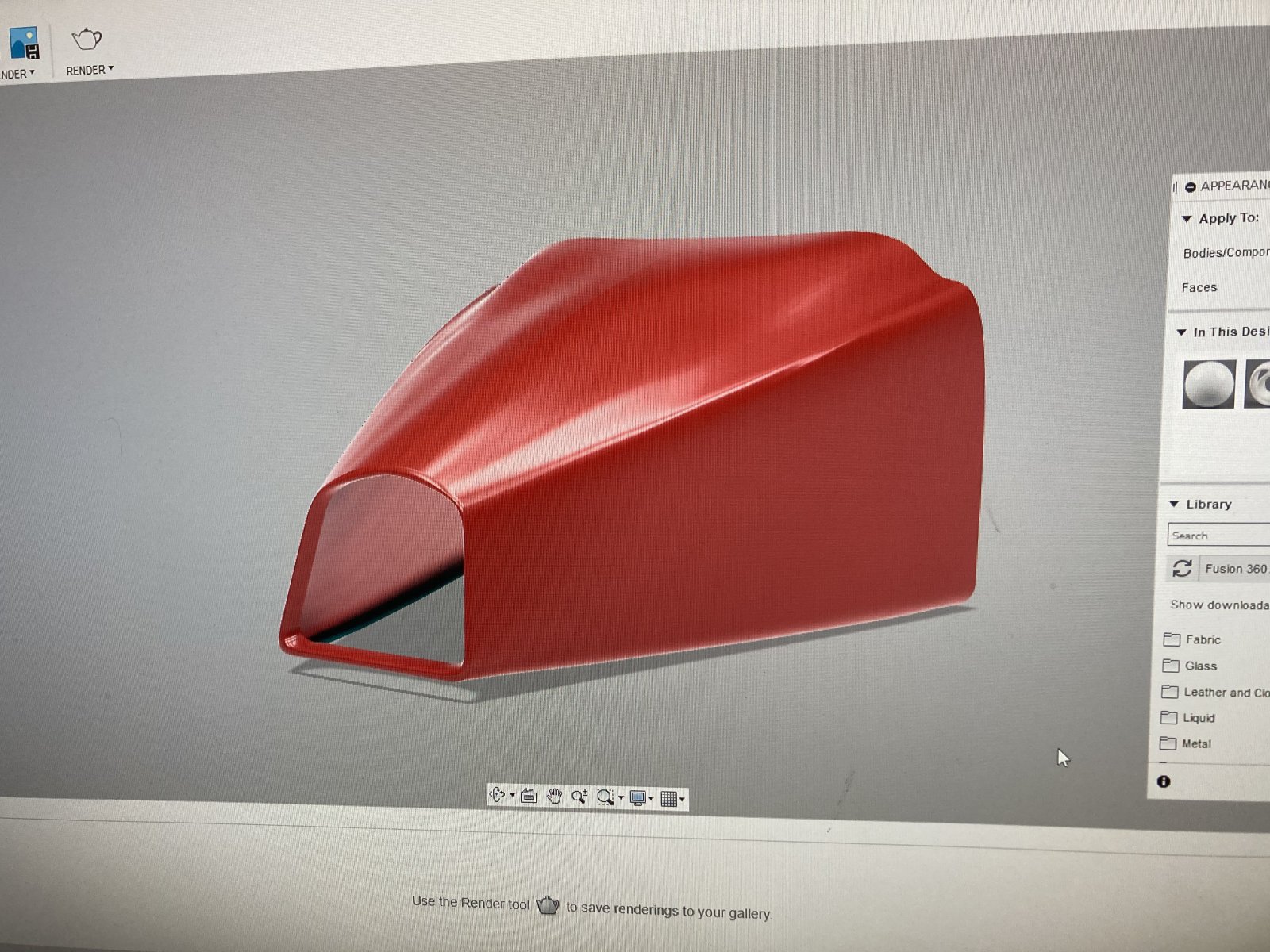
Ok. I finally figured out a technique all of my own for doing off plane modeling. Its tedious, but I was able to re-model the very forward nose section (which is a very **** complex shape). Much easier on the software as well. All surface form rendering. No dragging t-splines.
The rest should be easy. Just modeling in the lower front section, some minor profile adjustments, and the lower cutout.


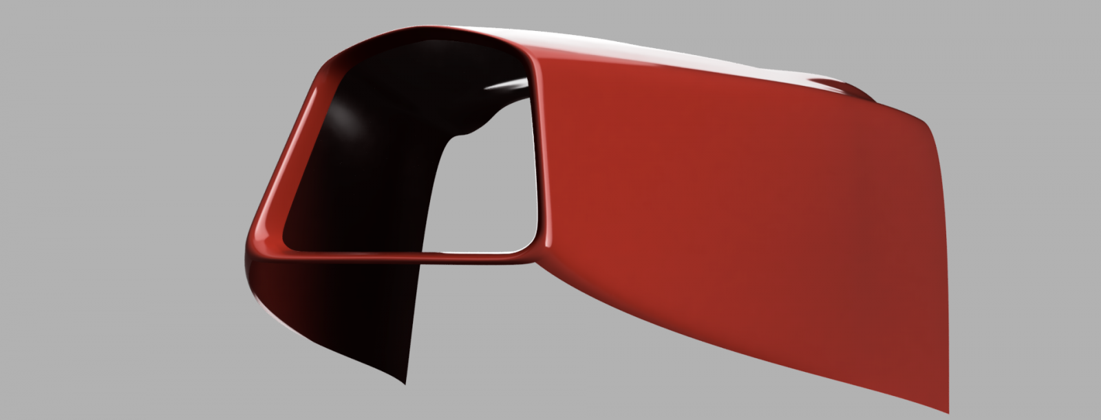

The rest should be easy. Just modeling in the lower front section, some minor profile adjustments, and the lower cutout.
Brian74
Goblin Guru
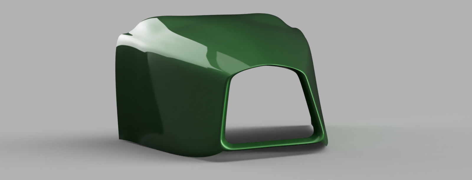
Little idea I had after I woke up in the middle of the night at 2am; taking shape…Lately I dream about CAD designing every night.
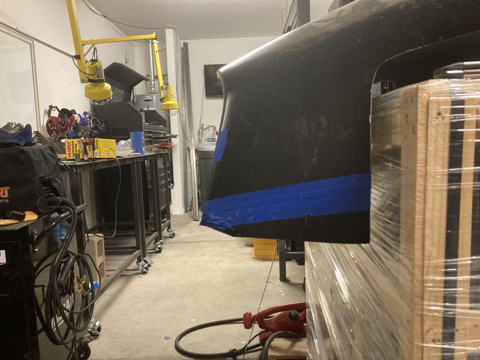
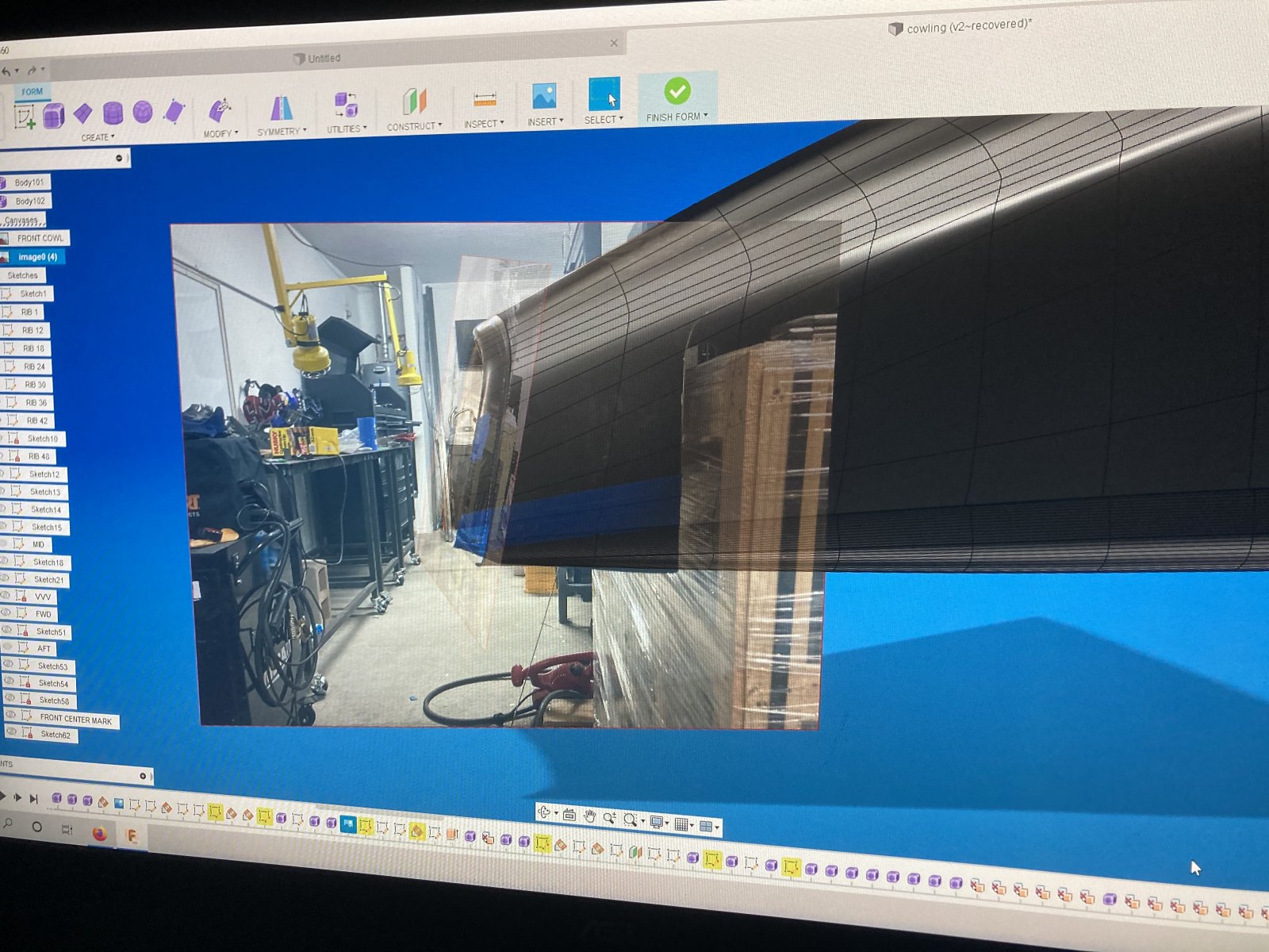
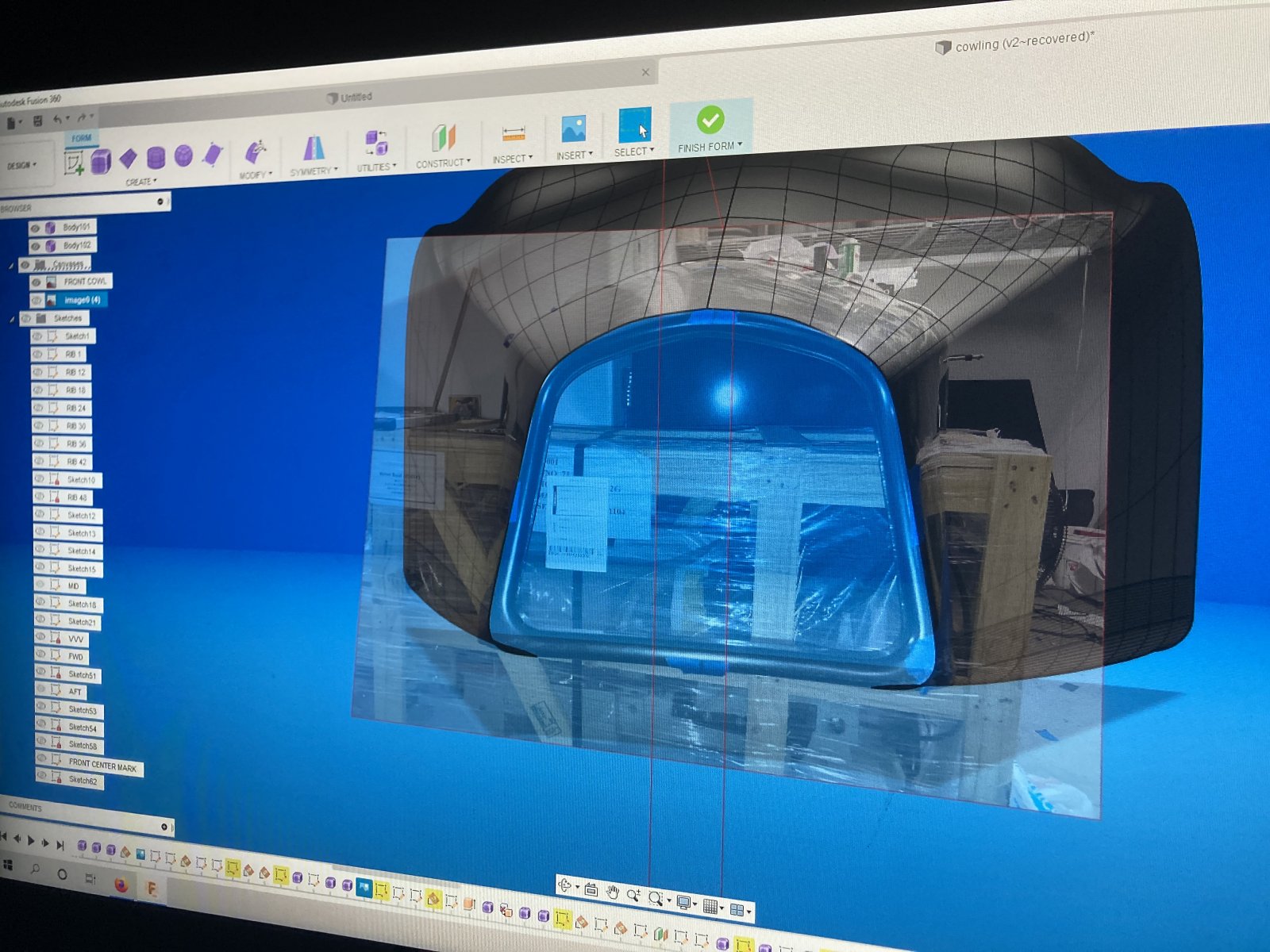
Playing around with more techniques… Without orthographic imagery, in CAD, the only use a photo is good for is following general 2D perspective shape contours. Measurements are still super critical if you want dimensional accuracy. I wish I knew a smartphone software developer, because an orthographic camera app would not be that difficult to design.
I guess if you are profiling a relatively simple, flat object, constraining it to the required dimensions would be super easy with a 2D perspective image. Lots of youtube videos on that… Certainly not the case here, though. I know soon enough that laser scanners are going to get even better and none of this **** will even be required.
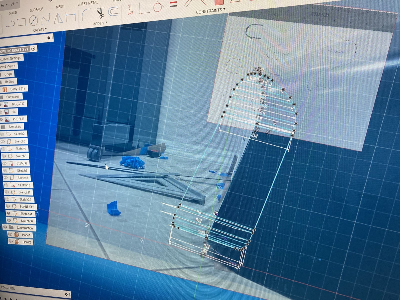
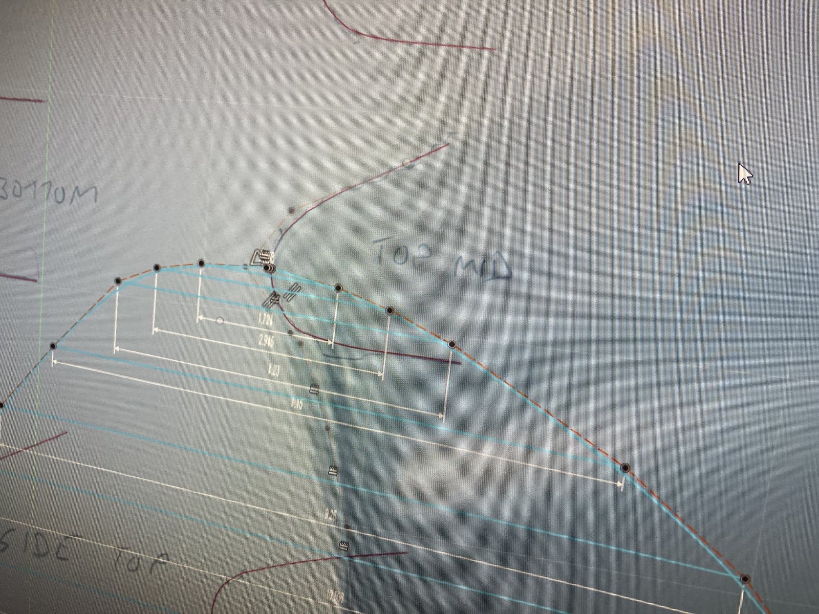
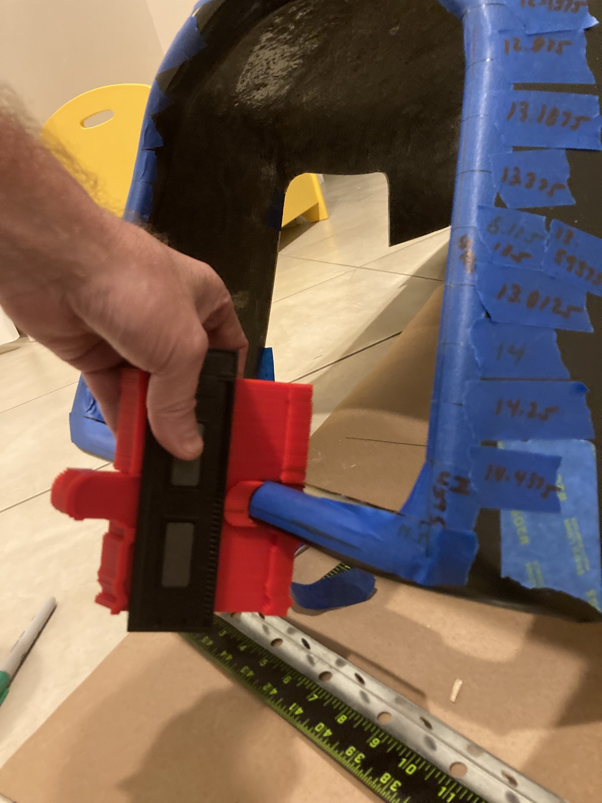
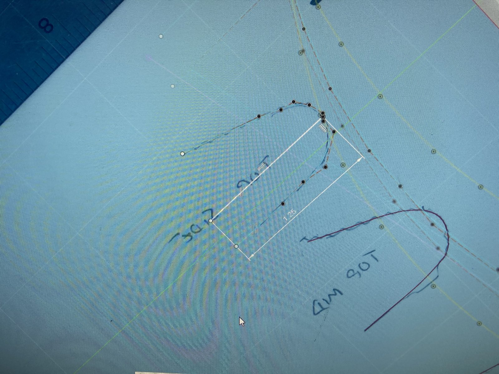
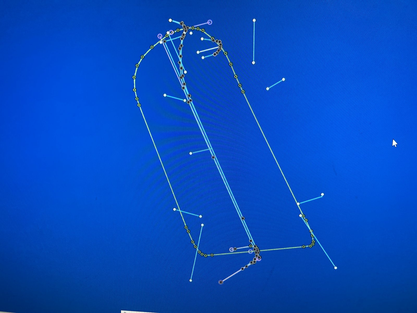
Now that I know what I’m doing, I decided to break this profile down with 5 additional planar references to get the front radiator opening curve rib profile dead-on perfect.
I am using a 1.25” 90 degree horizontal plane setback on all of the inside ribs, which will define every single point of the inner profile perfectly, and ahead of time. I should be able to connect those points and extrude the rear vertical plane right from that profile. I’m learning that the more planar data points that you can resolve from a single point reference, the better.
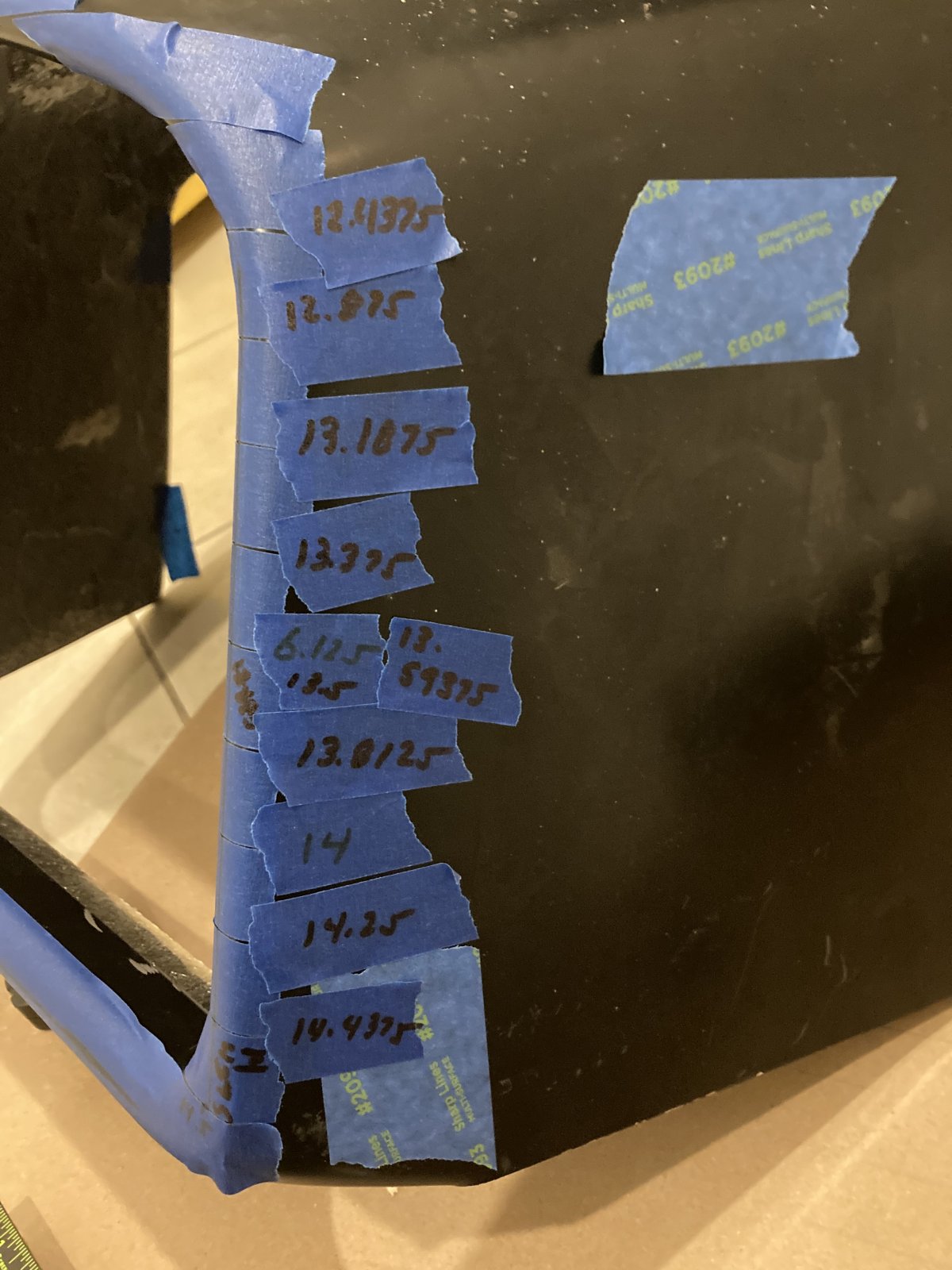
For my newest technique, I actually used a carpenter’s contour gauge to measure out the rib profiles, and then threw the tracings on my scanner (which is also an orthographic camera… Can’t get any more accurate than that!). I now will draw out the rib profiles on the respective planes of the 3D shape to connect the vertical profiles. I will use a coincident constraint to connect the ribs at the profiles. Should work, in theory, lol. It is so far, anyways…
That should get me well within 1/8” or better tolerance, and I learned another 3 or 4 new techniques in the process. This stuff is so much fun. Should have a final draft of this tomorrow.
Playing around with more techniques… Without orthographic imagery, in CAD, the only use a photo is good for is following general 2D perspective shape contours. Measurements are still super critical if you want dimensional accuracy. I wish I knew a smartphone software developer, because an orthographic camera app would not be that difficult to design.
I guess if you are profiling a relatively simple, flat object, constraining it to the required dimensions would be super easy with a 2D perspective image. Lots of youtube videos on that… Certainly not the case here, though. I know soon enough that laser scanners are going to get even better and none of this **** will even be required.
Now that I know what I’m doing, I decided to break this profile down with 5 additional planar references to get the front radiator opening curve rib profile dead-on perfect.
I am using a 1.25” 90 degree horizontal plane setback on all of the inside ribs, which will define every single point of the inner profile perfectly, and ahead of time. I should be able to connect those points and extrude the rear vertical plane right from that profile. I’m learning that the more planar data points that you can resolve from a single point reference, the better.
For my newest technique, I actually used a carpenter’s contour gauge to measure out the rib profiles, and then threw the tracings on my scanner (which is also an orthographic camera… Can’t get any more accurate than that!). I now will draw out the rib profiles on the respective planes of the 3D shape to connect the vertical profiles. I will use a coincident constraint to connect the ribs at the profiles. Should work, in theory, lol. It is so far, anyways…
That should get me well within 1/8” or better tolerance, and I learned another 3 or 4 new techniques in the process. This stuff is so much fun. Should have a final draft of this tomorrow.
Sparvy
Active Member
I'd be game for that when the time comes. My Goblin won't be back on the road till April due to the northeast weather though.I’m nearing prototype stage on the spoiler. I will eventually need 3 or 4 people to test out the prototype. I’ll sell the prototypes at my cost of the material ($175); in exchange for feedback.
AZmoto
Well-Known Member
I would be interested in that. I'm up the road in Chandler.I’m nearing prototype stage on the spoiler. I will eventually need 3 or 4 people to test out the prototype. I’ll sell the prototypes at my cost of the material ($175); in exchange for feedback.
Paul
SmsDetroit
Goblin Guru
I’d be in for the front spoiler.I’m nearing prototype stage on the spoiler. I will eventually need 3 or 4 people to test out the prototype. I’ll sell the prototypes at my cost of the material ($175); in exchange for feedback.
Scott #321
Well-Known Member
Definitely interested if you javelin the space for 1 more. I have a tilt hood so I would likely fabricate a mount option to account for that.I’m nearing prototype stage on the spoiler. I will eventually need 3 or 4 people to test out the prototype. I’ll sell the prototypes at my cost of the material ($175); in exchange for feedback.
OptimizePrime
Goblin Guru
I'd be interested in giving feedback!
You think the DF guys could have just sent you their rendering of the hood? What you have learned along the way is invaluable though, so I get it!
You think the DF guys could have just sent you their rendering of the hood? What you have learned along the way is invaluable though, so I get it!
Brian74
Goblin Guru
I kind of doubt DF has a CAD rendering of the hood/cowling; other than perhaps a few conceptual renderings Adam likely might have drawn up. From what I remember on my last visit, Lonny was telling me how they worked the mold by hand. To design a fiberglass mold from CAD would mean you would also need the automation to form/cut the mold.I'd be interested in giving feedback!
You think the DF guys could have just sent you their rendering of the hood? What you have learned along the way is invaluable though, so I get it!
All I can say, is that after I trialed my ass through this cowling mockup; this program is MUCH easier now.
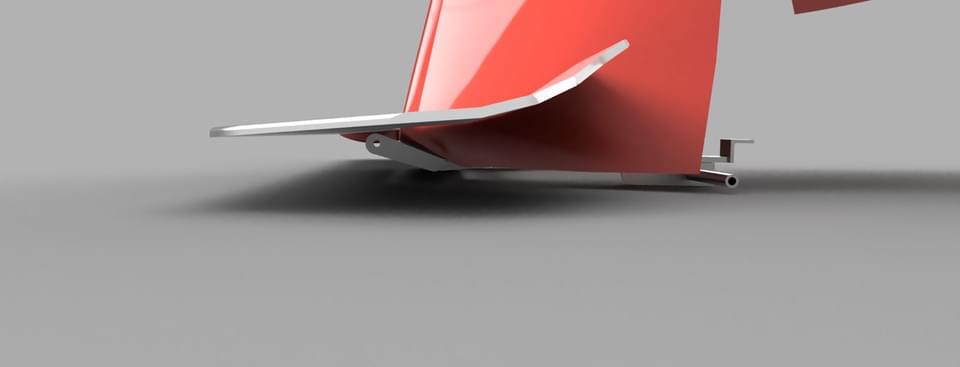
I revisited my spoiler design today after referencing a few more spoiler profiles. I made some changes that I think will make it easier to produce. Nothing rocket science here… just an airfoil shape, that can hopefully be tweaked for just the right amount of fwd downforce. KISS principal. This is not an F-1 car. I’m designing a simple solution to a simple problem while trying to make it affordable and easy to manufacture.
Really what I need to determine overall from the trial & error is the proper amount of required bend angle in the spoiler. Anything beyond effective is just drag. I did several measurements on the 9-lives spoilers; they are running up to 30 degrees overall, with similar surface area.
What I do love about Fusion 360 is that I can go on McMaster Carr and download anything in their catalog and import it to the CAD. I was having a hell of a time trying to find a low-profile fastener for my lower airfoil design. I was able to test-fit several of their fasteners until I found one that fit.
Literally… A sufficient flat plane drag surface area would solve the issue at hand without creating anywhere near enough enough additional drag to affect performance, but I’m down to make something a little more visually appealing.
Last edited:
Brian74
Goblin Guru
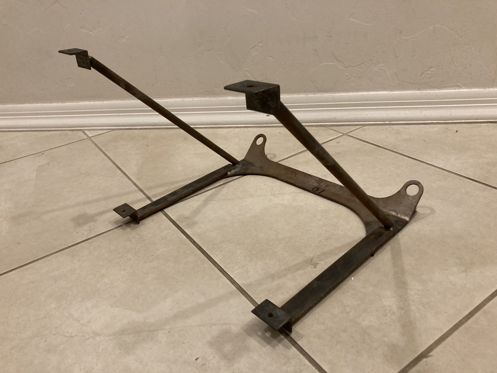
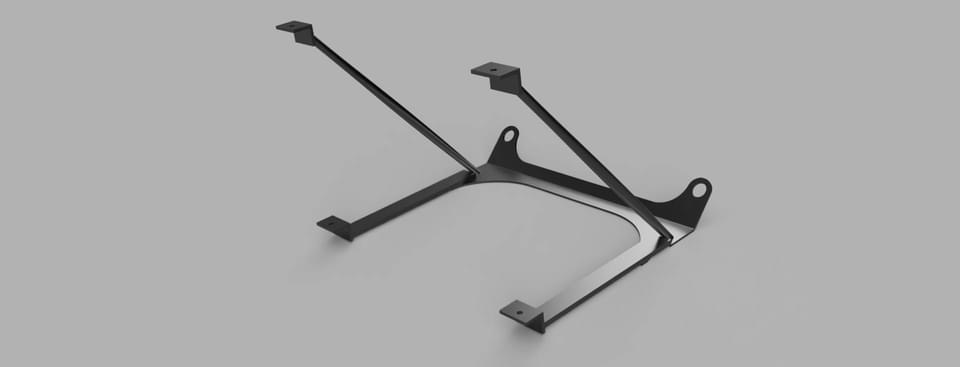
Rendered the radiator support in CAD. Was pretty easy given I know how to design part shapes now reasonably quickly.
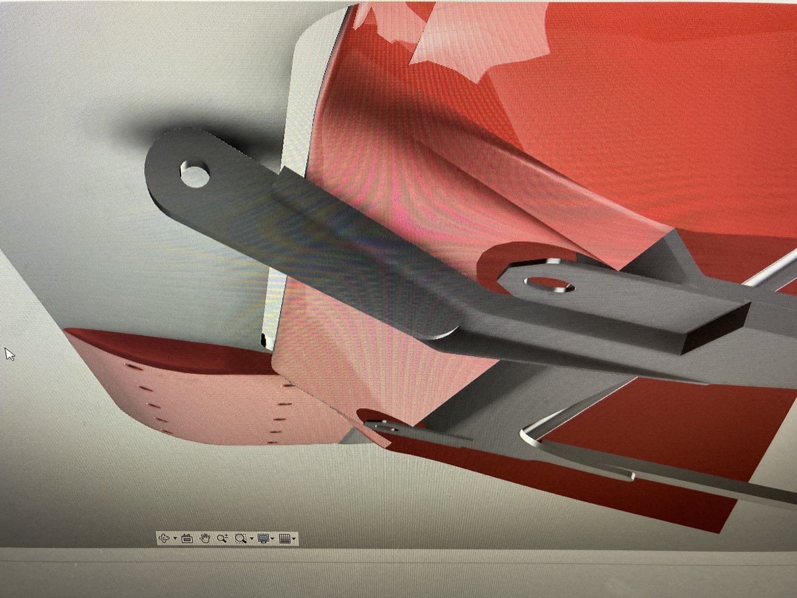
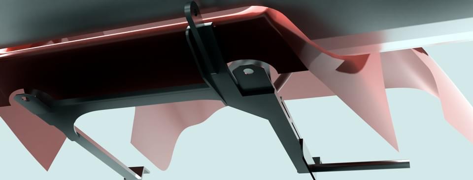
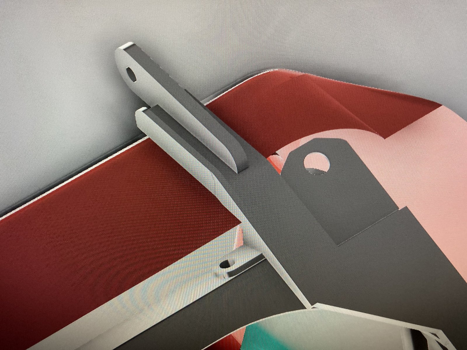
I started drafting out a mount for the spoiler. I’m trying to minimize any reduction in ground clearance while maintaining the strength of the mount. This requires some tight tolerances and I’m sure I will find a few areas later on that will need some adjustment. I am keeping the component breakdown simple so I can make changes later on if needed.
The mount brackets tie in to the existing radiator mount structure and will be full bolt-on after some mount hole drilling. Should be able to stand on the spoiler when done. I still need to resolve the rear bracket and add proper support there. That one is tough as there is limited clearance due to the radiator hoses.
I kind of doubt DF has a CAD rendering of the hood/cowling; other than perhaps a few conceptual renderings Adam likely might have drawn up. From what I remember on my last visit, Lonny was telling me how they worked the mold by hand. To design a fiberglass mold from CAD would mean you would also need the automation to form/cut the mold.
We finalized the design in cad and then machined wood bucks to pull molds from for each of our fiberglass components.
Engine cover being machined.
Sanding primer to fill in pores.
After that, we waxed and polished six or seven coats to make sure the mold would release.
This is the engine cover mold and a part pulled from it.
Brian74
Goblin Guru
Nice. I guess it was silly for me to assume you guys didn’t have the means to CNC machine the cowlings off of the CAD design, lol. I like this though… I see where the planar separation lines are on that cowling photo and most of mine are in the exact same spots; which tells me I was on the right approach mindset in developing mine.View attachment 30492
We finalized the design in cad and then machined wood bucks to pull molds from for each of our fiberglass components.
View attachment 30493
Engine cover being machined.
View attachment 30494
Sanding primer to fill in pores.
After that, we waxed and polished six or seven coats to make sure the mold would release.
This is the engine cover mold and a part pulled from it.
View attachment 30495