Cruise control
- Thread starter Mxdad303403
- Start date
I thought maybe I had wired it to the license plate light wire instead of the brake light (same LED module, 2 wires)...but no. That's not it. The resister only sees voltage when the brakes are applied.As another thought on wiring it wrong, it should only see voltage when applying the brakes.
Still hunting.
Assuming you got one of the aluminum body, finned resistors, the reason it's finned is to help dissipate heat. I would mount it somewhere that can get some airflow and against something that won't melt. Or you will have to go to a resistor with a higher ohms value. You also might want to confirm that the resistor actually measures the 6ohms if you haven't.
Joebob
Goblin Guru
My two cents as my cruise control works properly:
I have a 2008 2.4L Auto
Button panel cruise switch is press down to turn on. Other switches are momentary switches.
Cruise on/off is wired with the pink wires from the button wire kit
Used a 12" LED bar from Amazon for third brake light
Used a 50W25Ohm resistor that was wired in parallel to the third brake light wires. I wanted less Amps that the 6Ohm.
Wired onto the fuse box where the light blue wire goes to the resistor and the 3rd brake light and the ground goes to the resistor and third light.
The circuit only gets power when brake pedal pressed so haven't felt it heat up but never hot when checked after a ride.
Make sure you are going >25mph before trying to start cruise.
Make sure you brake switch is not active when not holding pedal (I had to loosen the hold down screw to let it float a bit)
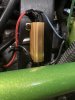
Resistor was placed after the car was up and running and as it could get hot, positioned on the fuse block in front of the large hole for heat dissipation and visual inspection.
Hope that helps solve a mystery.
Joe
I have a 2008 2.4L Auto
Button panel cruise switch is press down to turn on. Other switches are momentary switches.
Cruise on/off is wired with the pink wires from the button wire kit
Used a 12" LED bar from Amazon for third brake light
Used a 50W25Ohm resistor that was wired in parallel to the third brake light wires. I wanted less Amps that the 6Ohm.
Wired onto the fuse box where the light blue wire goes to the resistor and the 3rd brake light and the ground goes to the resistor and third light.
The circuit only gets power when brake pedal pressed so haven't felt it heat up but never hot when checked after a ride.
Make sure you are going >25mph before trying to start cruise.
Make sure you brake switch is not active when not holding pedal (I had to loosen the hold down screw to let it float a bit)
Resistor was placed after the car was up and running and as it could get hot, positioned on the fuse block in front of the large hole for heat dissipation and visual inspection.
Hope that helps solve a mystery.
Joe
I finally got around to checking mine. With my LED tail light, and the 6 ohm resistor in parallel, I measure 12.8 ohms to ground. It doesn't make a ton of sense to me, as it seems like it should be something less than 6.Rockauto listed the "high mounted brake" bulb as 13 watts which would be somewhere around 10-15 ohms.
The specs on the bulb I believe equated to around 13 ohms, but according to my Haynes manual, it looks like there are three bulbs in parallel in the stock housing. By my math, that means the stock assembly should have a resistance of about 4 ohms.
Unfortunately, cruise is still inop. I'm going to start checking clutch and brake switches next. I already checked them once, but maybe I missed something.
Where did you measure 12.6 ohms? Sounds like you have a lot of resistance in you wiring. But a lot of us have used a lot higher resistance than that without a problem. If you really want it to work you may have to get a tech2 clone so you can check the status of everything related to the cruise and see if you have any B or C trouble codes.
I measured between my solder joint where I tapped into the brake wiring on the positive side, and the frame of the car. Perhaps I have a bad ground somewhere?
I agree, I may be at the point where I need some more sophisticated tools to see what's going on with all the switches on the car.
I agree, I may be at the point where I need some more sophisticated tools to see what's going on with all the switches on the car.
Ark :D
Goblin Guru
Since I had the engine cover off this weekend for other reasons, I attempted to resolve my inoperable cruise control problem by removing the resistor I had in place (a 50-watt, 100-ohm), and replacing it with the 50 watt, 6-ohm one I purchased a few months back.
This did not fix my issue. After wiring the resistor in, I still see a constant 7.5 or so volts across the light blue wire without the brake pedal pressed in, and 13-14 volts with the pedal pressed in. So while I know I am using the correct circuit, it appears the ECM is not seeing a resistance load on the circuit that it expects and is thus, disabling my cruise control.
I do not have a third brake light. So, rather than the light blue wire running to the third brake light then ground, with a parallel connection ahead of the brake light, running to the 6-ohm resistor and then to ground, I simply have the light blue wire running to the resistor, then to ground.
@Lonny or anyone else, any thoughts? I do not really drive any highway, and this cruise control issue is not a huge priority, but I'd like to make it function if possible.
Ark :D
Goblin Guru
Not yet. Removing the hood is an event in and of itself, so I will do that next time I have a good reason to take the hood off. I've got a new dash piece being printed and I need to install a spacer between my mirrors and the mirror ears on the frame, so I have a good reason coming soon.Have you done any electrical measurements at the button panel? I had a bad solder on one of the switches that I only found with a wiring diagram and a multimeter.
Ross
Goblin Guru
Since I had the engine cover off this weekend for other reasons, I attempted to resolve my inoperable cruise control problem by removing the resistor I had in place (a 50-watt, 100-ohm), and replacing it with the 50 watt, 6-ohm one I purchased a few months back.
This did not fix my issue. After wiring the resistor in, I still see a constant 7.5 or so volts across the light blue wire without the brake pedal pressed in, and 13-14 volts with the pedal pressed in. So while I know I am using the correct circuit, it appears the ECM is not seeing a resistance load on the circuit that it expects and is thus, disabling my cruise control.
I do not have a third brake light. So, rather than the light blue wire running to the third brake light then ground, with a parallel connection ahead of the brake light, running to the 6-ohm resistor and then to ground, I simply have the light blue wire running to the resistor, then to ground.
@Lonny or anyone else, any thoughts? I do not really drive any highway, and this cruise control issue is not a huge priority, but I'd like to make it function if possible.
With 14v with a 50 Ohm load, (14/50=0.28) is only 0.28 amps, which at 14V is (0.28x14=3.92) 3.92 watts, the new 50 watt resistor is still well within its' working range. Electrically, you changed nothing, so no surprise it didn't fix anything.
I would start looking other places. Are the pedal switches working correctly? Switch panel working? Fuses? Grounds?
With the hood off, you could test the 2 resistors in parallel (25 ohms resistance) or in series (100 ohms). Maybe the ECM will recognize the load.
Last edited:
One of us is confused. His wattage is 50watt on both, with the resistance changing from 100 ohms to 6 ohms?The new resistor is the same resistance as the old one, the only change you made is that the new resistor can't handle as much power (watts).
With 14v with a 50 Ohm load, (14/50=0.28) is only 0.28 amps, which at 14V is (0.28x14=3.92) 3.92 watts, the new 50 watt resistor is still well within its' working range. Electrically, you changed nothing, so no surprise it didn't fix anything.
I would start looking other places. Are the pedal switches working correctly? Switch panel working? Fuses? Grounds?
With the hood off, you could test the 2 resistors in parallel (25 ohms resistance) or in series (100 ohms). Maybe the ECM will recognize the load.
Have we ever confirmed how many bulbs are in a stock 3rd brake light on the late models? 2 Bulbs parallel would would equate to 6 ohms, 3 bulbs would be about 4 ohms. If you have a way to measure your amp load on that circuit, it might be interesting to see what you get. I'll try and review the wiring diagrams this evening to see if I can tell anything about how it might should be working based upon where the bcm is measuring the current/voltage.
Ark :D
Goblin Guru
No worries, you had me questioning everything I thought I knew!I read it wrong. Sorry guys, I'm the goof ball who got it wrong.
6 ohms (2 bulbs) would be 14v/6ohms=2.33 amps, which is 32.66 watts.
4 ohms (3 bulbs would be 3.5 amps, which is 49 watts.
I will measure the current as soon as I can, but I have travel to Greensboro this week so it won't be until the weekend.
Sluggonaut
Goblin Guru
Not to hijack but I've been following this because I am in the same boat - cruise control is not high on the list, but would be nice to get it working.
Any more detail you can provide on that process for the electrically challenged? Is it continuity, resistance, or voltage checks and is it from one side of the switch to the other or from the switch to something else?Have you done any electrical measurements at the button panel? I had a bad solder on one of the switches that I only found with a wiring diagram and a multimeter.
What is the method for testing the pedal switches? Is there a voltage/resistance range to check for when the switch is activated?Are the pedal switches working correctly?
Ross
Goblin Guru
I use resistance testing to test switches. Put the test probe on both sides of the switch, and see how low the resistance goes when the switch is closed. Should be less than 1 ohm. Usually this can be done with the wires still on the switch, but disconnecting the wires on one side of the switch will give more accurate results.
If you look at a wiring diagram, you could follow the switch wires to see which wires are suppose to be ground or power, and do some voltage testing. So the pink wires are suppose to have 12V power, and when the switch is pressed, the 12V power should transfer over to the other side of the switch.
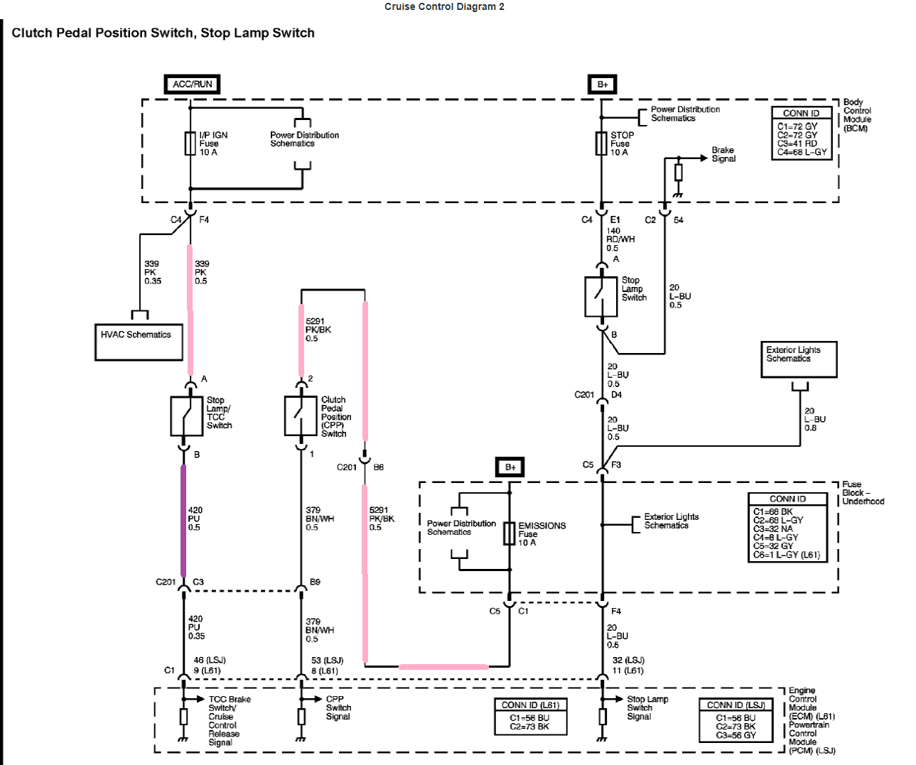
If you look at a wiring diagram, you could follow the switch wires to see which wires are suppose to be ground or power, and do some voltage testing. So the pink wires are suppose to have 12V power, and when the switch is pressed, the 12V power should transfer over to the other side of the switch.
Rauq
Goblin Guru
Linking to @Ross 's post here, and I'm a bit rusty, but here's what I recall.Any more detail you can provide on that process for the electrically challenged? Is it continuity, resistance, or voltage checks and is it from one side of the switch to the other or from the switch to something else?
If you measure resistance from the pink wire at the button switch panel to the gray wire, you should get an open circuit with the cruise control switch off. With the cruise control switch on, you should get about 8.25K Ohms. With the Resume/Accelerate switch depressed, you should get about 2.88K Ohms (inverse of the sum of the inverse resistances). With the Set/Coast switch depressed, you should get about 1.27K Ohms. The exact measurements aren't as important as their relevance to each other- I don't think DF uses resistors of the exact same value as GM, but they're close. If you don't get resistance readings like these, there's probably a wiring issue in the button panel. I will say, though, I'm the only person I know of who's found an issue in a DF-supplied button panel.