Desert Sasqwatch #155 Track (mods) - 08 SS/TC crate LNF F40

Desert Sasqwatch

Goblin Guru
In case no one was paying attention, I did drop several - some blatant - Easter Eggs in some of my prior posts to my build log about this project:
35207

35208

35209

35210

35211

Ain't drilling speedholes just because I like to (its all Racer X's fault). :p:cool:
 

Desert Sasqwatch

Goblin Guru
BTW, I've also been working on a resolution to what I see as a potential chassis stiffness item at the rear of the frame. I have nothing against the engineering that Lonny put into the design of the Goblin chassis. It is simple, buildable/manufacturable, lightweight, and more than adequate for a street driven Goblin with 'stock' Cobalt power and rear suspension.

What I am seeing is that many builders tracking their Goblin are reporting some handling issues that can't seem to be nailed down in the rear of the chassis. I'm not discussing the limitations of the McPherson strut suspension or the type of bushings used in the LCAs - there has been many discussions about this in the past. What I am looking at is the frame mounting points aft of the b-pillar for the subframe and where dynamic chassis loads will cause deflection in the frame - and subsequent changes in the suspension when the Goblin is pushed hard and/or has (potentially way more) increases in HP.

The biggest item I am seeing is the rearmost downbars - where the top bar, coming from the strut mount plate, intersects the middle frame bar and bends down to the subframe rear mount. This downbar, by itself, has no support in any direction. Bolting the subframe to the bottom of the downbars limits fore/aft motion, but not lateral motion. Note, the LCA rear mounting point attaches to this location and high lateral suspension loads are applied from this point

Also, the triangle 'ears' - consisting of the main bottom frame tube (where the radiator hose is routed forward) and the diagonal tube from the subframe front mounting plate forward to the b-pillar - have no lateral support. The suspension loads noted above for the rearmost downbars can travel through the subframe - which is assumed to be a rigid rectangle - and can impart these forces into the 'ears'.

The bottom of the b-pillar has a lateral chassis crossbar - 1 inch square tube - mounted several inches forward on the main frame bottom tubes and is interrupted by the tunnel (0.105ish 3X3 inch open channel). This combination of parts forms the front side of the narrow rectangle defined by the lower frame bars (triangle 'ears') and the bolted in front crossbar of the subframe. Under load, this rectangle can deform, and assuming the subframe remains rigid, will allow deflection of the rearmost downbars, and result in changes in the rear suspension geometry.

This is a simplistic explanation to try to define what I'm seeing from my engineering perspective. Other factors play into this view, which would further complicate this explanation. Example; the middle frame bars, tied into the engine and transmission side mounts through to the front and rear transmission mounts, will provide some lateral stiffness, but also impart a twisting moment to the 4 engine/transmission mounts.

I have been working on a solution for my Goblin and I will be providing an explanation and photos in the next several days. Most of what I'm working on requires additions to the frame and welding in triangulation bars. I've passed several different ideas through a frame design program (a very crude one), but it does indicate the additions I'm making create a marked improvement in the stiffness of the frame behind the b-pillar.

Again, I am in no way implying that the engineering of the Goblin chassis is flawed or unsafe. This exercise is a look at the ultimate loads that could be applied to the frame and subframe. It is directed for consideration and discussion to those builders who are (or will be) pushing their Goblins to the limits. More to come.
 

Desert Sasqwatch

Goblin Guru
And even more project progress pics - more measuring 200 times and cutting once, welding and grinding...
20220817_103735.jpg
20220821_154744.jpg
20220821_154753.jpg
20220821_154804.jpg


And I removed as much weight as possible from the wedges used to rotate my engine/transmission forward - lost 1.25 lbs from the original 2.5 lbs as purchased.
20220822_093907.jpg
 

Desert Sasqwatch

Goblin Guru
I now have the first part of this project completed, my new subframe. It is a far cry from the chunky, clunky
BN_caboose,_Eola_Yard,_1993.jpg

that looked so out of place on the 'lean' DF tube frame:
20220823_111021.jpg
20220823_111113.jpg


This new subframe is made from 2.0X2.0X0.120 square tube front and rear crossbars with 1.75X0.120 round tube sidebars and the triangulation bars are 1.0X0.095 round tubes. The 4 mounting bolt locations are sleeve bushings and the front and rear transmission mounts are fabricated from the 2X2 square tube. Speedholes are optional! :p
20220823_115325.jpg

20220823_115422.jpg


In finished form it weighs 31 lbs which is 9.5 lbs less and is more stiff than the Cobalt subframe, design rated for a 1000 lb lateral load on the sidebars plus a 50% margin. It is perfectly flat to the bottom of the main frame tubes - it doesn't hang lower like the Cobalt subframe - for a total flat bottom front to back on my Goblin.
20220823_115355.jpg


Please keep in mind I have several modifications that are not conventional, like the rotation of my engine/transmission forward, that required changes to the stock rigid transmission mounts. The new tube subframes that Lonny engineered fit the F23 and F35 transmissions, but do not appear to fit the F40 - the rear bottom case extends back about 3 inches more - and would interfere with the rear crossbar.

To answer the next question, no, I am not making these to sell. I do have all the measurements that I could provide to anyone interested. Yes, it takes some good fabrication and welding skills - and a better welder than I have - but it is doable. The end result is the basis for the second part of this big project, and as you can guess my Goblin needs a rear suspension now. It is a clean slate and a fully independent UCA/LCA is in the ideas stage - with lots of inputs from Dale E. ;) More to come.
 
Last edited:

Ross

Goblin Guru
Nice! Flat bottom, light and strong. The rear suspension is the part I am looking forward to, as I also want upper control arms.
 

Ross

Goblin Guru
I'm being patient, and jealous. Still trying to figure out what you are going to do for rear uprights. I like how you added extra bracing in the rear of the car, got me wondering if I am getting frame flex there.
 

Desert Sasqwatch

Goblin Guru
Dale and I have had some lengthy discussions about this and I touched on this in my post from yesterday talking about the stiffness issues I'm seeing with my engineering eye.
 

Ross

Goblin Guru
Dale showed me his latest suspension ideas earlier this month, and left his carboard mock up control arms with me. You are an early adopter!
 

Desert Sasqwatch

Goblin Guru
I've got a mockup zip tied to my frame right now and some questions and discussion points open with Dale. My frame is a special case, since I have the F40 mod, and the driver's side dimensions are different than the passenger's side. I will have some build discussion on ths with some photos soon.
 

Desert Sasqwatch

Goblin Guru
A peek at what I'm working on for the rear suspension - just a mockup for gross dimensions and mounting point locations.
20220825_091641.jpg

Still have a lot of design engineering to do, the smallest dimension changes are making a big difference for the angles of the UCA, LCA and drive axle.
 

Desert Sasqwatch

Goblin Guru
While I'm bored (NOT!) waiting on materials to show up, I broke out the CADboard to play with a valve cover channel cover idea:
20220903_100129.jpg
20220903_100142.jpg

It would be made of fiberglass, so no chance of electrical issue with the spark plug coils. Just another thing to occupy my time tinkering until I get the rear suspension fully designed and fabricated. :cool:
 

JBINTX

Goblin Guru
While I'm bored (NOT!) waiting on materials to show up, I broke out the CADboard to play with a valve cover channel cover idea:
View attachment 35472View attachment 35473
It would be made of fiberglass, so no chance of electrical issue with the spark plug coils. Just another thing to occupy my time tinkering until I get the rear suspension fully designed and fabricated. :cool:
That area is indeed a rock collecting gutter.
 

Desert Sasqwatch

Goblin Guru
BTW, I've also been working on a resolution to what I see as a potential chassis stiffness item at the rear of the frame. I have nothing against the engineering that Lonny put into the design of the Goblin chassis. It is simple, buildable/manufacturable, lightweight, and more than adequate for a street driven Goblin with 'stock' Cobalt power and rear suspension.

What I am seeing is that many builders tracking their Goblin are reporting some handling issues that can't seem to be nailed down in the rear of the chassis. I'm not discussing the limitations of the McPherson strut suspension or the type of bushings used in the LCAs - there has been many discussions about this in the past. What I am looking at is the frame mounting points aft of the b-pillar for the subframe and where dynamic chassis loads will cause deflection in the frame - and subsequent changes in the suspension when the Goblin is pushed hard and/or has (potentially way more) increases in HP.

The biggest item I am seeing is the rearmost downbars - where the top bar, coming from the strut mount plate, intersects the middle frame bar and bends down to the subframe rear mount. This downbar, by itself, has no support in any direction. Bolting the subframe to the bottom of the downbars limits fore/aft motion, but not lateral motion. Note, the LCA rear mounting point attaches to this location and high lateral suspension loads are applied from this point

Also, the triangle 'ears' - consisting of the main bottom frame tube (where the radiator hose is routed forward) and the diagonal tube from the subframe front mounting plate forward to the b-pillar - have no lateral support. The suspension loads noted above for the rearmost downbars can travel through the subframe - which is assumed to be a rigid rectangle - and can impart these forces into the 'ears'.

The bottom of the b-pillar has a lateral chassis crossbar - 1 inch square tube - mounted several inches forward on the main frame bottom tubes and is interrupted by the tunnel (0.105ish 3X3 inch open channel). This combination of parts forms the front side of the narrow rectangle defined by the lower frame bars (triangle 'ears') and the bolted in front crossbar of the subframe. Under load, this rectangle can deform, and assuming the subframe remains rigid, will allow deflection of the rearmost downbars, and result in changes in the rear suspension geometry.

This is a simplistic explanation to try to define what I'm seeing from my engineering perspective. Other factors play into this view, which would further complicate this explanation. Example; the middle frame bars, tied into the engine and transmission side mounts through to the front and rear transmission mounts, will provide some lateral stiffness, but also impart a twisting moment to the 4 engine/transmission mounts.

I have been working on a solution for my Goblin and I will be providing an explanation and photos in the next several days. Most of what I'm working on requires additions to the frame and welding in triangulation bars. I've passed several different ideas through a frame design program (a very crude one), but it does indicate the additions I'm making create a marked improvement in the stiffness of the frame behind the b-pillar.

Again, I am in no way implying that the engineering of the Goblin chassis is flawed or unsafe. This exercise is a look at the ultimate loads that could be applied to the frame and subframe. It is directed for consideration and discussion to those builders who are (or will be) pushing their Goblins to the limits. More to come.
After much analysis, playing with my crude frame design program, and hands on testing with a rubber hammer (for checking harmonics) and lever arms (2x4s to apply torque forces), the simplest solution to the previously indicated issue for the unsupported rearmost down tubes is this:
20220910_081719.jpg

A crossbar (1.25 inch) between the rearmost 'ears' and diagonal tubes (1 inch) from the bottom of the down tubes up to this crossbar. This forms a rigid, triangulated box that keeps the rear subframe mounting points from moving laterally as previously explained. This will make about a 60% improvement in the rigidity of the rear subframe mount.

Edit: BTW this will work for all subframes - Cobalt, the DF prototype/new production, or anyone else's design.

In my case, with the extensive mods I'm making with UCAs, I made the addition of these horizontal diagonal tubes (1 inch):
20220910_081730.jpg

Which add about another 30% to the rear frame mount rigidity - but is mainly added for structure to increase rigidity at the UCA mount locations. These horizontal diagonal tubes do not need to be installed to see a potentially marked improvement in rear frame rigidity. Note, the crossbar and horizontal diagonal tubes have been seen in several previous photos.

By increasing the rearmost part of the frame/subframe rigidity, the front subframe mounts and the 'ears' in this location are subject to lesser lateral forces. They should be adequate as designed.

Reminder: this is only a discussion about ultimate loads that could potentially be applied to the Goblin frame. I am not making any implications that the Goblin frame is unsafe in any manner as designed and delivered by DF.
 
Last edited:

Sluggonaut

Goblin Guru
I'd be afraid to add this rigidity to mine solely due to how much I had to move my right downtube to get my subframe to go in.

That being said, those downtubes need reinforcement because it doesn't take much force to move them laterally, or in any direction.
 

Desert Sasqwatch

Goblin Guru
Build update:
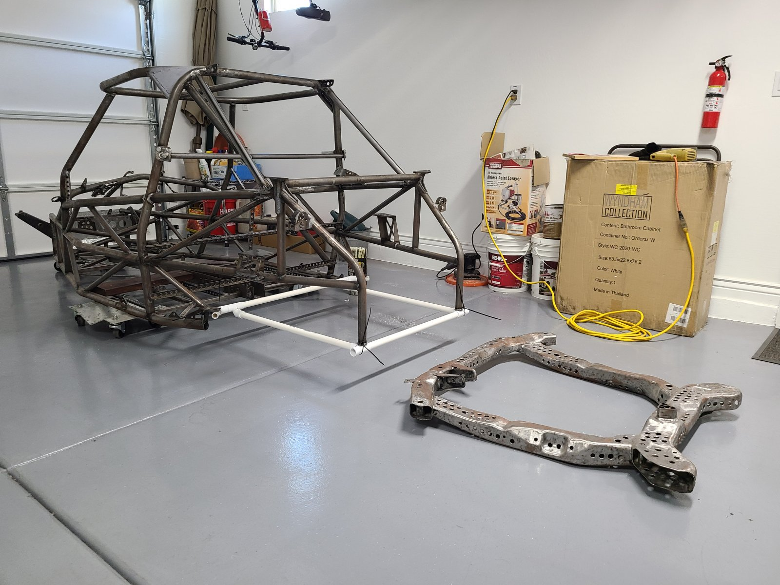
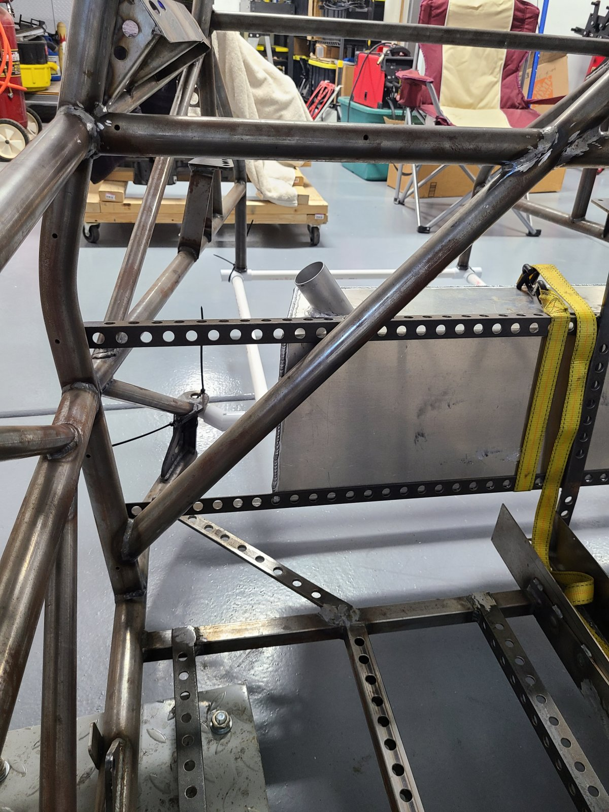
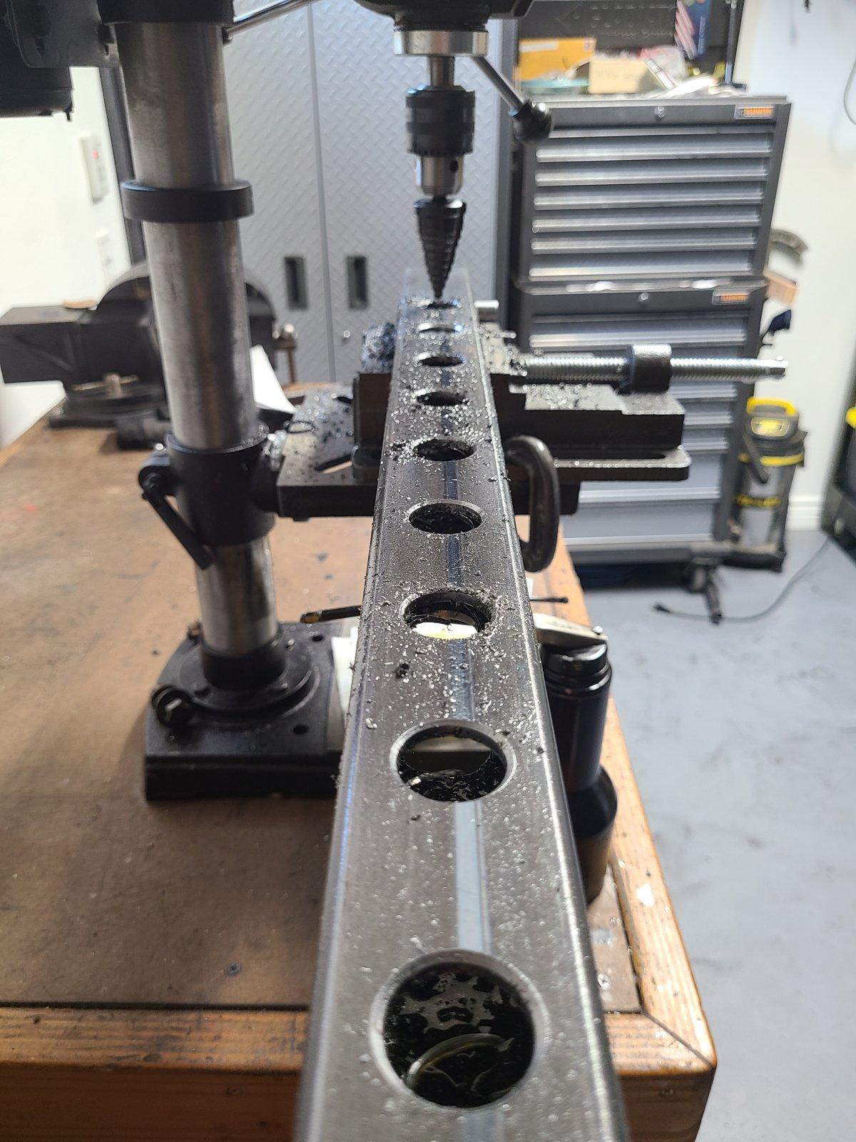
So after all the measuring, cutting, drilling, grinding, making certain that everything is straight, square and plumb - and the final welding of all triangulation bars to stiffen the frame to my satisfaction - I have finally finished the major modifications to my DF frame. Its been a long time coming, about 2 1/2 years, of analyzing, designing, and fabrication (with several turnbacks to start over). :D

Yep, I added some weight to both the front and rear, but it is now as strong as it can be made using the minimum number of triangulation pieces (10 total). My inner engineer is now satisfied with the end result. There are still numerous small brackets and tabs to be added (nothing complex), which will be worked when I finally start assembling the dry mockup - which is hopefully not too far off in the future.

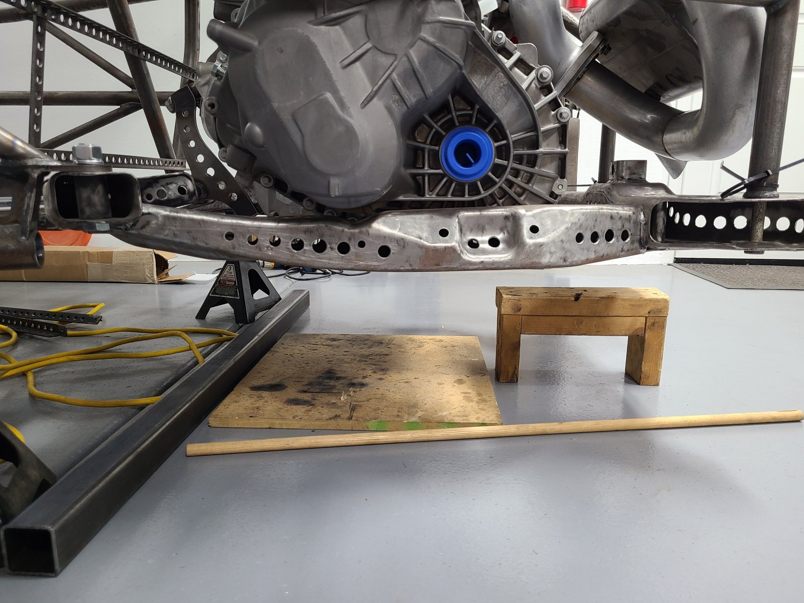
However, the rear suspension project is in full swing, which is the long pole in the tent. Waiting on materials to show up so it can continue. I did decide to fabricate new aluminum uprights, rather than try to use the Cobalt uprights:
20220912_094743.jpg

The machining of these blocks will be a chore and I hope I don't turn these into expensive scrap. :oops:

Another item that is slowing things down is locating correct drive axles. I cannot fabricate the UCAs/LCAs until I have the axle lengths. The F40 requires a shorter (by almost 2 inches) axle on the driver's side. I did not purchase the ZZP F40 kit with the axle, so I'm trying to source one with no luck. ZZP or their supplier does not sell this axle outright and a custom axle is $1200 for just the driver's side axle. :( If someone has insight to locating this axle, please let me know.

So, plan B is to locate the shortest GM axle for the driver's side, with the same spline counts and shaft nose geometry, and then locate a passenger's side axle that is 2 inches longer. Example: driver side is 22.5 inches, the passenger side would be 24.5 inches. I may need to buy several axles to swap stub ends around to get the correct splines and nose dimensions. The Double Bonus for going this way is the rear track will be wider to correct for the reported narrower stance at the rear and the UCAs will be longer to help with the camber gain geometry. ;)

More to come. Keep it Squatchy!
 
Top