High speed GMLAn
- Thread starter Lokian
- Start date
Goblin Graber
Well-Known Member
Were they the ones that went to the ABS module? If so you’re good. They will get extended later to connect to the BCM.
no i think they went to the black VCIM. The car had no ABSWere they the ones that went to the ABS module? If so you’re good. They will get extended later to connect to the BCM.
Ross
Goblin Guru
The GM high speed LAN, when the harness is completed, goes:
1. OBDII port, tan wires to the
2. Power steering unit, then brown wires to the
3. BCM, then tan wires to the
4. PCM, because my donor had a manual transmission.
Since you have an automatic, it probably goes to the ECM then the TCM? Let us know!
1. OBDII port, tan wires to the
2. Power steering unit, then brown wires to the
3. BCM, then tan wires to the
4. PCM, because my donor had a manual transmission.
Since you have an automatic, it probably goes to the ECM then the TCM? Let us know!
Brian74
Goblin Guru
Two data wires, high and low (tan & tan/blk). They daisy chain everything together in series so certain modules know what other modules are doing. At the front of the bus, you have the ECM; at the back of the bus you have the Power Steering Module. Each of those have a 120 ohm resister to provide voltage drop and signify bus termination.
You can see there are different modules on the bus, depending on what options the car came with. You can see that the TCM, VCIM, and EBCM are bypassed if the car did not come with these modules.
For the Goblin, all we need to worry about is that these two bus wires run continuously from the ECM. We remove the brake control module and VCIM, so they will bypass those. Where they previously entered those modules, we cut the harness and patch those two wires to the exiting wires of the module similarly as it shows in the diagram.
What is most important is to ensure the bus remains intact, otherwise the modules will not communicate with each other.
Goblin Graber
Well-Known Member
The 3 digit codes in the boxes are RPO codes that are in the trunk. LAP is your engine for example, LNF is the turbo.can anyone explain to me how to read this?
View attachment 19729
The “X” number to the left of a wire is the connector number with the pin location on the right. That will be a number of letter depending on the connector.
The four digit numbers like 2500 are the circuit number with the wire color underneath.
Ross
Goblin Guru
The Data Link Connector is GMs name for the OBDII port.
Pin 6 and 14 are the tan/black and tan wires that go to the
Power steering module, on pin 1 and 2 of that connector. You can see "connector views" to find the pin numbers for each connector.
Leaving the Power steering module on pin 4 and 5 are the brown/white and brown wires, heading to the BCM.
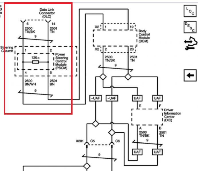
After the BCM,
if you have the UAF option, you will have a Driver Information Center, which I think is on the turbo cars that allows them to pick a gauge display, that was mounted on the A pillar where the boost gauge was on a supercharged car.
Then our Goblins don't use the VCIM, or the EBCM modules, so we would connect the wires to the ECM for a manual car, or TCM for the automatics.
Pin 6 and 14 are the tan/black and tan wires that go to the
Power steering module, on pin 1 and 2 of that connector. You can see "connector views" to find the pin numbers for each connector.
Leaving the Power steering module on pin 4 and 5 are the brown/white and brown wires, heading to the BCM.
After the BCM,
if you have the UAF option, you will have a Driver Information Center, which I think is on the turbo cars that allows them to pick a gauge display, that was mounted on the A pillar where the boost gauge was on a supercharged car.
Then our Goblins don't use the VCIM, or the EBCM modules, so we would connect the wires to the ECM for a manual car, or TCM for the automatics.
Last edited:
OKKKKK .. you guys all are my heros. Thank you for explaining it and how to read those diagrams.
Because I removed VCIM. I cut the wires C5 and C6 at x201 and A and B at X101. I now need to connect wires 2 and 20 on X2 (which is on the dash harness) to A and B on X101. Correct?
Once again ty all. Without this forum and the support of all it would be impossible.
Q
Because I removed VCIM. I cut the wires C5 and C6 at x201 and A and B at X101. I now need to connect wires 2 and 20 on X2 (which is on the dash harness) to A and B on X101. Correct?
Once again ty all. Without this forum and the support of all it would be impossible.
Q
Joebob
Goblin Guru
Not to hijack but I am about to start the stripping process of the wiring this weekend and the only thing that confuses me in the videos is the handling of the data wires. But, from looking over the diagram and the discussion, I think I have an idea of how to interconnect the wiring. I have a 2.4L auto so does the red wire paths look correct?

That looks correct to me but I followed the video's until I started cutting out twisted pairs. Look for tan and tan/black wires. Follow them and make sure they create a line from start to finish. Best bet is to ask questions if you don't know or think you know. Cut only what you are sure of and leave a little slackNot to hijack but I am about to start the stripping process of the wiring this weekend and the only thing that confuses me in the videos is the handling of the data wires. But, from looking over the diagram and the discussion, I think I have an idea of how to interconnect the wiring. I have a 2.4L auto so does the red wire paths look correct?
View attachment 19979
View attachment 19979
") Also get to know which connector is which (ie x201) that way you can look at the the pins and trace back the wires to where they came from to verify what they are if needed.
Also get to know which connector is which (ie x201) that way you can look at the the pins and trace back the wires to where they came from to verify what they are if needed.Anks329
Well-Known Member
Not to hijack but I am about to start the stripping process of the wiring this weekend and the only thing that confuses me in the videos is the handling of the data wires. But, from looking over the diagram and the discussion, I think I have an idea of how to interconnect the wiring. I have a 2.4L auto so does the red wire paths look correct?
View attachment 19979
View attachment 19979
Take a look at my question and then Lonny's response in this thread: http://dfkitcar.com/forum/index.php?threads/new-videos.1402/post-30182 I had almost messed up the data wires, but Lonny's post saved me from a bigger problem later on.
viperbmw69
Active Member
Can someone please check my logic on Data Wires? 2008 LS base manual. L61
TN and TN/BK I have pinned them out to the following
1. OBD port
2. EPS
3. BCM X2 pin 2 and 20
4. X101 Connector (Engine to Main Harness connector) Pins A and B
Comes out of A and B on engine side harness. then I lost it.......
5. ECM No voltage....... on X1 Pins 43 and 44
I see that the X101 connector have another set of TN/TNBK wires on another set of pins... What are these for?
Do I simply need to spice BCM X2 Pin 20 to ECM X1 Pin 44 and BCM X2 pin 2 to ECM X1 pin 43??????? This would eliminate the X101 connection correct?
Attachments
-
 176.9 KB Views: 118