Joel's "new-to-me" standard track Goblin #007 - '10 SS/TC manual

Jm12

Active Member
For today's incremental progress...
PXL_20210827_124000882.jpg

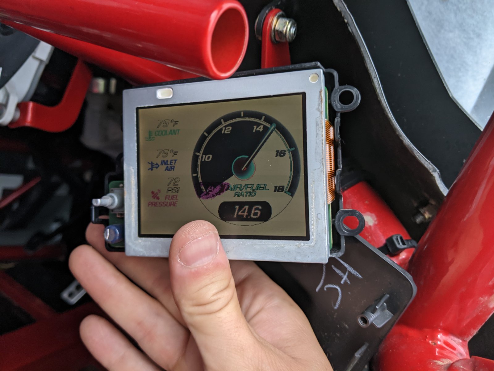
The RPD lives! I popped the housing open, took every ribbon cable off and anything else that wasn't soldered in place, gave it a quick wipe, reseated and here we are.

I'm amassing a pile of parts to start replacing this weekend. Plugs, coil packs, intake filter, catch can, replacement safety harness, hub and bearing assemblies for the front, fuel line and splitter to vent the tank, 3rd brake light to get CC working (purchased in Moab but never installed). I'm going to clean the MAF sensor as well and hopefully between that, a filter that isn't hopelessly clogged, and the new ignition bits, the misfire (?) problem will be resolved. I also managed to source a bushing cover plate for the shifter from an Amazon seller after multiple attempts to contact the original eBay seller went unanswered. $16 to replace the o-rings that are holding it in place currently seemed reasonable enough.

Once all that is taken care of the car should finally be back to baseline and then I can move on to actual improvements.
 

Jm12

Active Member
Working on changing out the safety harness today. Got to the right half of the lap belt and the bolt spun. This is what I was hoping not to see in the tunnel.
So... I guess I'll be running the old harness for a while longer. On to the next thing.
 

Attachments

Jm12

Active Member
Working from small to large in terms of progress (and setbacks)...

Driver's side mirror has been replaced and wired up, and the missing retaining plate on the side of the shifter has been replaced. Nice little fit and finish things that work back towards baseline and reduce anxiety. The RPD died again after reassembly, but I think it's a loose connection and at least I know at this point that I can bring it back to life.

I got a bike rack installed up top. On the front I used the same u-bolts that I'd used to mount the cargo box, and in the back I repurposed one of the spare brackets from the rearview mirror. I'll probably look for something stronger for the back mount but for now it works. For anyone who's curious, these are the u-bolts that I've used for both the bike rack and the JEGS cargo box: https://www.amazon.com/gp/product/B093SNPTFF/ref=ppx_yo_dt_b_search_asin_title?ie=UTF8&psc=1
PXL_20210911_225554550.jpg
PXL_20210911_230406700.jpg
PXL_20210911_225912882.jpg
PXL_20210911_225950579.jpg
PXL_20210911_225931856.jpg


Enough of the components for the steering wheel went on sale that I couldn't resist replacing it. A deep dish wheel put the steering wheel too close so I ended up doing a flat and slightly smaller wheel which seems to be just about right. It does accentuate just how high the steering wheel sits- I really wish I could get it lower without a ton of hassle. I've bought some 1x2x4" aluminum billets to play with- I'm hoping they'll make nice spacers for lowering the wheel without cocking it farther to the right, and they'll probably come in handy for future endeavors.
PXL_20210929_122512131.jpg
PXL_20210929_122524543.jpg
PXL_20210929_121748699.jpg


To add to my growing list of things to do- wheels. This thing needs different wheels. I knew I'd need a set of 15x10s for race days, but I I'd like to run the same size for street as well. Unfortunately the number of soft compound road legal 15x10" compatible tires is pretty limited, so I have to decide whether I want to lock myself into a very limited tire selection or just run 15x8" for the road. Either way, I'm pretty sure 2 sets of JEGS SSR Star wheels are in my future. An AutoX buddy has a CNC mill and has offered to redrill the hubs, but he's a couple of hours away and there might be some trial and error there. I'm debating on whether I should do this or just drop the $400 on 4 new hubs direct from DF to save the time, anxiety, and potential frustration. Suspension will come first, but wheels will be a fast follower.

On to the biggest part. A couple/few weeks ago I changed the intake filter, spark plugs, coil packs, and a cleaned the MAF sensor, and some combination of those seems to have seems to have remedied the misfire issue. No more weirdness under WOT. If I had to take a guess I'd say that it was a single overgapped spark plug that was causing it, but it wasn't a bad time to change out those other things anyway. Unfortunately, last night I pulled off the MAF sleeve to find everything full of oil once again. I'm also getting a strong odor of unburnt fuel at speed that wasn't present previously, but that might have something to do with the intake filter's orientation up in the wind- I'm just not sure and I'm running into issues quicker than I can learn about them and resolve them. I've been reading up as much as I can on LNF PCVs, blow by, and more serious potential problems, but I feel like I'm coming up short. If anyone has any input in this department I would be most appreciative.
PXL_20210929_005030784.jpg
PXL_20210929_005052389.jpg
 
Last edited:

JBINTX

Goblin Guru
Here is some info pertinent to your PCV query:


Gtstorey

Goblin Guru
Actually, I'm not sure that the catch can I posted would help your problem, it is the one that goes on the PCV system. I started looking at catch can systems with Mighty Mouse Catch Can | LSX | Mopar | Ford | Mightymouse Solutions | Virginia, USA and they recommended their "race" RACE Can (mightymousesolutions.com) can for the connection between the engine and intake pipe, he referred to it as the " high flow liquid separator". He also recommended both cans to be closed top.

I got distracted by other issues and haven't followed up anymore.
 

Jm12

Active Member
You might consider this, seems to be the best price I've seen for a dedicated Ecotec Catch can set up.
RPM Ecotec Catch Can System (rpm-motorsports.com) See below.

I think the amount of blow by is very excessive though (depending on how much you have driven since you cleaned it) and you may have more serious problems.
This is my concern as well. How interconnected are the vacuum lines, PCV, and turbo? I'm fairly positive that the vacuum lines are not set up correctly and I've yet to address it- I've been bouncing between the vacuum lines and the PCV issue without making much progress yet on either.
 

Gtstorey

Goblin Guru
Below is the drawing I made for Mighty Mouse Support. The fitting farthest to the driver side on the valve cover ties to the intake tube before the turbo. I'm not using the DF supplied tube.

The passenger side valve cover fitting with the SS braided line, connects to the turbo and is the PCV line. The vacuum line is the line with the green cap and I think runs to a boost controller mounted on the intake.
27305
 

Jm12

Active Member
The two tubes coming off the valve cover on my car are routed like yours (and everybody else's) I think.

My understanding is that the far left tube that runs to the cold air side next to the MAF sensor is the fresh air intake and shouldn't be flowing in the direction that it is flowing- that's the job of the braided tube on the right- but the actual PCV valve is under the exhaust manifold on the other side of the engine. It sure looks like both of these hoses come out of the valve cover, so I just can't imagine how they're supposed to behave differently without a check valve on one side. Looking at post #8 from this thread, I just don't see how the stock fitting for the cold side needs to be that big without having a check valve as part of it. What am I getting wrong here?
 

Attachments

Gtstorey

Goblin Guru
I think the pcv valve is inside the valve cover. The other tube has what is probably a check valve on it in the stock set up. You may just need a check valve if you don’t have one.
 

Jm12

Active Member
I'm reading the same posts all over the internet over and over. I'd read this one before, but I overlooked a critical detail along with the author of that critical detail. See post number 11 in this thread: https://www.cobaltss.net/forums/2-0l-lnf-performance-tech-153/pcv-install-305568/

Powell Racing indicates here that there is a check valve built into the stock fresh air inlet. They also say that there should not be oil coming back through that line, but one step at a time.

Are none of the TC Goblin builds running check valves on this line?
 

Rauq

Goblin Guru
I don't know why there would be a check valve in the intake tube line. I thought there would be one in the intake manifold line. I thought the theory of the design was two-fold:

In vacuum, the line going to the intake manifold (post-turbo post-throttle body) pulls a vacuum on the crankcase (check valve open), and the line going to the intake tube (pre-turbo, pre-throttle body, post-MAF) provides filtered + metered air to be pulled through the crankcase.

In boost, the line going to the intake manifold sees pressure so the check valve closes. The line going to the intake tube essentially reverses its flow and sits somewhere between venting excess crankcase pressure or pulling vacuum through a venturi effect from its intake tube connection point.

Granted, I don't have an LNF, so I don't know the quirks, but this is also essentially the LSJ setup except that the intake manifold portion is built into the intake manifold, we don't have a hose for that portion.
 

Desert Sasqwatch

Goblin Guru
@Rauq you got most of it correct, let me help fill in the rest for the LNF.

The 2 ports in the valve cover are located in rear corner by the turbo. The closest to the corner of the valve cover is the line going to the inlet side of the turbo. This line, which goes through baffling in the valve cover, will be under constant but somewhat variable vacuum depending upon the turbo RPM. This is also the line that should get an oil catch can to keep as much oil vapor out of the turbo compressor as possible. The other port is the air feed line from the intake tube. It has a one way check valve to allow air to flow into the valve cover. The reason for this is to keep any positive crankcase pressure - and oil vapor - from getting into the intake tube and ultimately into the turbo compressor. The sizing on these hoses is not super critical since they are on the 'ambient ' side of the turbo.

The PCV is in the intake manifold on the LNF and is open under vacuum to allow a specific amount of air into the intake to pull down any crankcase pressure. Under boost the PCV is closed, so the above mentioned vacuum line going into the turbo inlet - which is pulling a lot of vacuum with high turbo RPM - is the path to vent the crankcase pressure. Unfortunately the PCV does not have any baffling to help remove oil vapor from the metered air under vacuum and it will end up in the intake manifold and coke up the back of the intake valves. If the PCV happens to fail, boost pressure will blow back into the crankcase and try to find another vent, which could damage the intake tube check valve and blow air and oil vapor into the inlet side of the turbo.

The PCV port is probably more important to have an oil separation/catch can than the turbo side, but it it much harder to accomplish. The intake manifold must be modified to bypass the stock PCV location, port the air to an external oil vapor collection device, through a property sized external PCV, and then back into the intake manifold. This set up will still function identically as the stock system but help keep most of the oil vapor from ending up on the back side of the intake valves. There are a couple companies who have kits for this type of system - Dr. Google can find them. :D
 

Gtstorey

Goblin Guru
Mine has the stock check valve as pictured above, its just been relocated since it would have stuck out so far mounted directly to the intake tube. This is basically in the stock location (line between valve cover and intake tube, post maf, pre turbo) as shown in post 9 in the cobaltss.net link above. There is a description from Powell Racing of how the LNF system works here http://dfkitcar.com/forum/index.php?threads/oil-separator.1596/post-28271
I'm not sure what the connection that he refers to from intake manifold to the lower engine is, but since I used the new ATK long block, it could be I just didn't notice it. He does mention the other line also, with a check valve.

I have heard of people using something like this on these lines, don't know how well they work.
check valves | McMaster-Carr
 

Desert Sasqwatch

Goblin Guru
Mine has the stock check valve as pictured above, its just been relocated since it would have stuck out so far mounted directly to the intake tube. This is basically in the stock location (line between valve cover and intake tube, post maf, pre turbo) as shown in post 9 in the cobaltss.net link above. There is a description from Powell Racing of how the LNF system works here http://dfkitcar.com/forum/index.php?threads/oil-separator.1596/post-28271
I'm not sure what the connection that he refers to from intake manifold to the lower engine is, but since I used the new ATK long block, it could be I just didn't notice it. He does mention the other line also, with a check valve.

I have heard of people using something like this on these lines, don't know how well they work.
check valves | McMaster-Carr
If the line is from the intake - vacuum bypass valve - it could be the line to the vacuum reservoir mounted on the front of the engine under the intake manifold.
 

Jm12

Active Member
[EDIT: for some reason this didn't post the first time I hammered the button and I see that there's a good bit more conversation since I wrote it. I'll clean it up later based on the info above, but if it directly contradicts any of the newer messages it's because I didn't see them before I posted the conjecture below]

[EDIT2: I think I got it mostly right?]


Here's another looong thread about this that I haven't finished reading thoroughly, but it has the best pictures and diagrams I've found yet: https://www.chevyhhr.net/forums/2-0l-performance-tech-46/installing-oil-catch-can-54350/page7/

Here's my understanding- and I could be way off in the weeds here but I think the problem is that there are two lines coming off of the crank case are related to, but are not, the PCV valve. That's on the other side of the engine, post turbo, under the intake manifold as you describe. I believe that both of these lines come off of the crankcase and both reverse flow under boost when the PCV valve closes. Without a check valve on the fresh air intake it blows nasty stuff further up the cold side- this would have been true for the stock configuration as well without a check valve built into the line. Why there are two lines instead of one is something I do not understand.

Maybe I'm completely off base here and someone can set me straight. Regardless of how right or wrong I am and how this thing should be routed, the amount of oil I'm seeing just can't be right. I'm going to try to do a compression test this weekend and possibly a leak down test if the cheapie tester that I've got in the mail even remotely works.
 
Last edited:

Jm12

Active Member
Going back and reading the newer replies after my out of order post, it sounds like my tenuous grasp of how the system works is sufficient for the moment, and I'm good to run a check valve on the fresh air inlet. I think I still have underlying problems that need to be addressed, but that should be sufficient for the moment while I figure those out. I've got these on order from Amazon and will probably run out to AutoZone to grab a $2 check valve tonight so that I can swing out to Ecotec Nation tomorrow since the dragon is basically my backyard.
 
Top