Joe's All Terrain #396 - 06 2.4L SS/NA Auto

averageJOEschmo

Active Member
Finally getting around to starting a build log...

My 12 y. o. son and I have enjoyed working on a few projects lately, the most recent being bringing a 1980 Honda Trail 110 back to life, and we wanted to build a kit car together. The goblin's affordability, fun factor and the great customer support sold us on the idea of jumping in on one.

We decided to go for the All Terrain version as we love to go off-roading and didn't see us using it much on the track. We may have changed our minds if we knew how few A/T's there are out there because we are very novice mechanics and are going to need a lot of help through this process.

A summary of our build:
2006 2.4L SS/NA with Automatic Transmission Donor
5 lug wheel hubs
All Terrain Kit
Extended chassis
 
Last edited:

averageJOEschmo

Active Member
Here are some photos of the process so far...

Welding the frame:
34615

34616


Stripping the donor:
We started with a 2.2L 2010 but then I found a 2.4L 2006 and decided to change plans. The 2010 had been in a fender bender so we stole parts from the 2006 to fix it up. Now its my daughter's car.
34618


34617


34619


Then we moved on to the 2006:

34620


34621


34622
 

averageJOEschmo

Active Member
Hello DF Goblin Family,

I am looking for some help with questions I have as I work on the wiring harness. I don't have much mechanic or electrical experience so most of this is very new to me and a bit daunting.

My donor is a 2006 2.4L SS/NA Auto with ABS

Questions:

#1
I am looking at labeling the body to dash connectors and have a few discrepancies from the labels linked to the videos which is making me nervous. Below is a diagram of the wiring of my body to dash connector. It is organized by pin location and shows the color of wire, what it connects to on the main/body harness, and what it connects to on the dash harness. The connections in red are the ones that are indicated by the base labeling sheet to preserve and extend. The connections in blue are ones that I think should be preserved and extended. Some of the wires from the body to dash connector go to three connectors that I'm not sure of where they plug into. One is a 5-pin connector located near the radio, the other two are 2-pin connectors that are in the same bundle that go to the pedal box.
Here are the things I need to clarify before I start cutting wires:
a) The connection at B10 appears to be for the Radio, not the Key Lock Actuator. Is there a different connection I should be looking at for this?
b) The connection at D4 appears to be tied to the brake lights, not the OBDII power. It looks like the OBDII power is coming from D3 which also powers the front acc plug. I assume I should keep the connection at D4 for the brakes?
c) Should I keep the connection at C3 for the brake pedal?
d) Should I keep the connection at D8 for the gear selector?
e) Do I need to keep any of the connections from B6 and B9, or from B5 and F6 BCM, the two unknown 2-pin connectors by the pedal box?
f) Do I need to keep any of the connections to the unknown 5-pin connector by the radio (I am assuming no)? The connections are: A4 body/dash connector, B12 body/dash connector, black ground, pink F5 BCM, and purple 71 BCM)
g) Are there any other things I should be concerned with or aware of?
35034


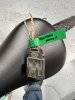
#2 Is this the engine harness connector? (wiring harness video part 4 @ 3:04)This picture is the connector on the main harness that I am assuming is the engine harness connector. I'm just confused as mine is much smaller than the one shown in the videos. The tan & tan/black twisted wire are the data wires, the green is the back-up lamp and the brown connects to B5 on the red BCM multiplug, then to position 18 on the ECM.
35035


#3 I don't have a coolant level sensor (or at least I don't think I do). Is that normal on some models? (wiring harness video part 4 @ 2:06)

#4 Is the light blue wire that is wrapped separately, the center brake light wire? (wiring harness video part 4 @ 3:18)

#5 I don't have a vacuum sensor connector (wiring harness video part 2 @ 1:48) Is this normal on cobalts with ABS?

#6 I just wanted to verify I did this correctly as my EBCM connector is different from the videos.
#1 is a large red w/ black stripe wire that connects to position B1 on the smaller rectangular light gray multi-plug in the main fuse box. (i removed it)
#2 is a pink wire that connects to position B2 on the dark gray square multi plug in the main fuse box (i believe this can be used to power the intercooler which i don't need so i removed it).
#3 is a gray (or maybe light blue) wire that connects to position F4 on the gray multi-plug then to position 7 on the ECM connector. should I remove?
#6 and 7 are tan and tan w/ black stripe twisted wires that connect to position C5 & C6 on the Dash connector.
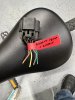
#4 and 5 are tan and tan w/ black stripe twisted wires that connect to the connector I mentioned in question #2.
The second image below shows what I plan to do with the twisted wires, is this correct?
35036

35037
 
Last edited:

Devo

Member
It’s been months since I reworked the wiring, and my donor is different, but I’ll try to help where I can. Full disclosure, I also haven’t gotten to the first start phase yet, so I have no reference if I’ve done it correctly myself. :)

#2 – I don’t believe the plug in your picture is the “body to engine” connector. If memory serves, there is a very similar looking plug in the engine bay near the driver side strut tower. It better matches the number and gauge of wires you’re referencing.
35061


#3 – Checking against the Rock Auto catalog between the different engine options, it appears that your configuration does not have a reservoir level sensor.

#4 – You should end up with two light blue wires in the area near the fuse box. The heavier gauge wire gets used for the radiator fan, while the other, I believe, is for the third brake light. One of the later “Organizing the Main Harness” videos shows the split out of the tail lights.

#5 – My donor also had ABS and the corresponding plug. As it gets cut out, I wouldn’t worry about it.

#6 – Refer to “Thinning the Main Harness, Pt.1” 1:34-2:30. Ultimately, the whole mess gets cut out, as the Goblin won’t be running ABS. Per the video, make sure to save the wire you cut out. I ended up using quite a bit of it while extending the wires later on in the process. Additionally, always leave yourself a couple inches of wire length next to the plug in case you need to either reattach or more easily reference colors.
 

averageJOEschmo

Active Member
Thank you very much Devo, follow up question:
#2 – I don’t believe the plug in your picture is the “body to engine” connector. If memory serves, there is a very similar looking plug in the engine bay near the driver side strut tower. It better matches the number and gauge of wires you’re referencing.
I have two 4-pin connectors that are similar and trying to make sure I get them right. It seems that most have a 8-pin connector. Does the one in your photo have the ambient temp sensor wires in it?

#3 – Checking against the Rock Auto catalog between the different engine options, it appears that your configuration does not have a reservoir level sensor.
THANK YOU for checking on that!
 

averageJOEschmo

Active Member
I took a look at my box of wire trimmings for applicable plugs. The one that best matches your photo got labeled as “headlight harness”. Unfortunately the wire colors don’t match - see photos.
Thanks for your help and taking time to look into this!

I got on to Alldata.com and found my connectors:

This is the one I was questioning and now found:
35076


I think this is the one you are referring to:
35077
 

averageJOEschmo

Active Member
Thanks @Devo and @Ross for your help!

Alldata connector diagrams helped me answer my questions or at least feel confident enough to move forward with the next steps. Just getting into the 4th video now. I'll be so relived when I get through this and can start it up with out issues....
35111
 

averageJOEschmo

Active Member
Progress is slow... but steady. We have most of stage one complete and the engine is mounted. Following the videos and looking to forum has made the process straight forward. Now we are starting to venture past the videos and things get more fuzzy.
37041

37042
 

averageJOEschmo

Active Member
I'm trying to figure out how to route and connect the hoses to the radiator and I can't seem to find the answers in the videos or forum. The hose and radiator provided don't seem to be compatible.

The hose provided with the kit is 1", they gave me a lot, way more than I need for connecting the radiator on the back and I assume the 1" hose is necessary for pulling through the frame, which I don't need to do but is seems to small to connect to my engine or radiator.

The connections on the radiator are 1 1/2", seems way too big to get the 1" hose on :
37043


And the connection on the engine seems to be 1 3/8", which also seems too large for the hose:
37044


Stock hose vs the kit hose:
37045


I haven't found reducers or couplers or any other radiator hose components in my kit. Am I missing something here?
 

Ross

Goblin Guru
I had little metal tubes that have different size rubber hoses on each side. Hose clamps were able to seal the hoses on the smaller tubes.
 

baustin

Well-Known Member
The kit at least used to, mine looked something like this:
37046

The coolant tubing that was pulled through the frame only needed to be a few inches out of the frame and then the tubing sized changed with these connectors and hose clamps. Just don't cut the tubing at the frame rail before you've test fit all the hose parts into place to make sure you're lengths work out.

Looks like it's still supposed to be included:
37047


If you can't find any of these in your part sets, then I'd reach out to DF about missing parts.
 

averageJOEschmo

Active Member
The kit at least used to, mine looked something like this:
View attachment 37046
The coolant tubing that was pulled through the frame only needed to be a few inches out of the frame and then the tubing sized changed with these connectors and hose clamps. Just don't cut the tubing at the frame rail before you've test fit all the hose parts into place to make sure you're lengths work out.

Looks like it's still supposed to be included:
View attachment 37047

If you can't find any of these in your part sets, then I'd reach out to DF about missing parts.
Thanks for your help!
 

Joebob

Goblin Guru
I'm trying to figure out how to route and connect the hoses to the radiator and I can't seem to find the answers in the videos or forum. The hose and radiator provided don't seem to be compatible.

The hose provided with the kit is 1", they gave me a lot, way more than I need for connecting the radiator on the back and I assume the 1" hose is necessary for pulling through the frame, which I don't need to do but is seems to small to connect to my engine or radiator.

The connections on the radiator are 1 1/2", seems way too big to get the 1" hose on :


And the connection on the engine seems to be 1 3/8", which also seems too large for the hose:


Stock hose vs the kit hose:


I haven't found reducers or couplers or any other radiator hose components in my kit. Am I missing something here?

See if this works. You will have to slow it down as Lonny works pretty fast.


Joe
 
Top