Lark's Track Goblin No. 40 - 2008 LT ***REGISTERED***

k.rollin

Goblin Guru
Separate finances means I don't need to concern myself with that.

No mistakes made, just a joke that didn't quite land as intended.
 

k.rollin

Goblin Guru

k.rollin

Goblin Guru
A cashier's check for $197.50 and some paperwork have just been sent off to Olympia so I'll have personalized plates representing WWU in about 8 weeks
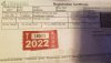
I'm still waiting for the plates, but the registration certificate arrived with the personalized number: AD LTNS = add lightness. Fitting as my donor was in the 1LT trim with a curb weight of 3,216 lbs and the build weighs in at 1,460 lbs.
 

Attachments

k.rollin

Goblin Guru
So I'm finally getting around to wiring up my dash buttons so they'll actually do something other than make people snicker but I'm having some issues with getting the desired result. Part of the issue is not being especially electrically savvy and the other is extreme fatigue, so I'm hoping one of y'all might be able to get me straightened out. What I want is for the switches to be illuminated whenever the key is on, and for the function (horn, flashers, etc.) to work when the button is depressed. The current result is the switch illuminates as it should, but regardless of the button's position, the flashers don't turn on, horn doesn't beep, etc. I have been working to my interpretation of the annotated photo below. The sketch is my interpretation. Please tell me where I've screwed up?
24120
24121
 

Ross

Goblin Guru
What is that a picture of? Is it an illuminated 3 pole switch? Do you know the internal electrical connections?
What is the switch suppose to do? That switch is suppose to operate the horn and flashers? So confused.

Lets work one issue at a time. The horn should work whether the ignition is on or not, or whether the back lighting in the switch is on or not. I think the horn has a fuse and a relay. Are those working? If so, does the horn work if you hook it straight to 12V?
 

Waterdriver

Goblin Guru
So I'm finally getting around to wiring up my dash buttons so they'll actually do something other than make people snicker but I'm having some issues with getting the desired result. Part of the issue is not being especially electrically savvy and the other is extreme fatigue, so I'm hoping one of y'all might be able to get me straightened out. What I want is for the switches to be illuminated whenever the key is on, and for the function (horn, flashers, etc.) to work when the button is depressed. The current result is the switch illuminates as it should, but regardless of the button's position, the flashers don't turn on, horn doesn't beep, etc. I have been working to my interpretation of the annotated photo below. The sketch is my interpretation. Please tell me where I've screwed up?
View attachment 24120View attachment 24121
Do you have an Ohm meter?
You can use the meter to find the switched poles by operating the switch and see if you get continuity.
From the schematic, I would start with points #1 and #2. The 1 to ground and the 2 to ground.
 

k.rollin

Goblin Guru
These are illuminated DPST switches, terminals 1 and 2 are normally closed (and therefore ignored for the purposes of DIC, horn, and hazard switches) and terminals 3 and 4 are normally open. There are four of these switches (info, return, hazard, horn), so none of them are pulling double duty or anything.

Horn and flashers work as expected when connected without a switch. My issue is that I'm braindead and can't wire the switch so that it functions properly.
 

Ross

Goblin Guru
So the horn works, great. The horn wire at the dash just needs ground.
Now we need to get the switch to give ground when the button is pressed.

So 3 and 4 are normally open. So that mean they are connected together when the switch is pressed?
Check with a meter:
Put the meter on Ohms resistance measure. Should indicate no connection.
Then connect the meter's 2 probes together, the meter should measure 0 resistance, or maybe something low like 8 ohms resistance.
Now , connect the probes on 3 and 4 switch. Meter should read no connection.
Press the button, and the meter should read something low like 8 ohms.

If it passes these tests, we just need to connect 3 to ground, and 4 to the horn wire.
 

Waterdriver

Goblin Guru
Try horn wire to post #4 and ground post to, well, chassis ground.
The volt/ohm meter set to ohm's will show you the open/closed circuit when the switch is operated.
Harbor Freight has basic inexpensive ones for around $10. An invaluable tool to have for any electrical work. Takes the guesswork out it.
 

k.rollin

Goblin Guru
3 to the dash wire and 4 to ground will actuate the horn or flashers depending on which dash wire I use. It turns out the switch was lit up because the horn and flashers are always hot. Since I want the switch LEDs to turn on with keyed power, I was running the pink dash wire to the positive terminal and negative to ground. This doesn't work because it seems that the pink wire isn't reading 12V.
 

k.rollin

Goblin Guru
Black Friday sale on a driver mod, if anyone else in WA is interested. I took too long to book my class this past summer, so I'm doing June 29th, 2022 instead.

 
Last edited:

k.rollin

Goblin Guru
A cashier's check for $197.50 and some paperwork have just been sent off to Olympia so I'll have personalized plates representing WWU in about 8 weeks
The actual wait time was closer to 8 months than it was to 8 weeks, but the personalized plates finally arrived!
29027
 
Last edited:
Top