LED Headlight, Turn Signal & Brake Wiring
- Thread starter OptimizePrime
- Start date
Ark :D
Goblin Guru
@Torchandregdoc
I just realized, after re-looking at this thread, that I never answered why I think Lonny recommended a resistor that can handle 50W of current. I think that reason is, the original poster of this thread is talking about running third-party taillights that separate the brake and turn signal connections, so Lonny was recommending to run from the CHMSL to power the brake lights, thus presenting more current load on the resistor.
In this scenario, you're simply picking your resistor based on the current your circuit would draw, exceeding it a little as to avoid burning up the resistor. I went with a 2W. I'll find out in time if I am right or not.")
I just realized, after re-looking at this thread, that I never answered why I think Lonny recommended a resistor that can handle 50W of current. I think that reason is, the original poster of this thread is talking about running third-party taillights that separate the brake and turn signal connections, so Lonny was recommending to run from the CHMSL to power the brake lights, thus presenting more current load on the resistor.
In this scenario, you're simply picking your resistor based on the current your circuit would draw, exceeding it a little as to avoid burning up the resistor. I went with a 2W. I'll find out in time if I am right or not.
JBINTX
Goblin Guru
Just for another data point. I installed this one.
Gave the other three to other builders.
It works.
https://www.amazon.com/gp/product/B00DCULNXS/ref=ppx_yo_dt_b_asin_title_o04_s00?ie=UTF8&psc=1
Gave the other three to other builders.
It works.
https://www.amazon.com/gp/product/B00DCULNXS/ref=ppx_yo_dt_b_asin_title_o04_s00?ie=UTF8&psc=1
Torchandregdoc
Goblin Guru
I bought and installed these as well. Put one between the turn and ground on each side in the rear. That fixed my rapid blinker probelm, but I still have the brake light problems. They do get super hot, but I guess that's to be expected since they are going directly to ground.Just for another data point. I installed this one.
Gave the other three to other builders.
It works.
https://www.amazon.com/gp/product/B00DCULNXS/ref=ppx_yo_dt_b_asin_title_o04_s00?ie=UTF8&psc=1
I also put a 100ohm resistor to ground on the CJMSL circuit, but that didn't fix my probelm either.
I have no brake lights when you push the brake pedal, but I do have them any time it's in gear. Also, when you let off the throttle, the engine rpm drops to idle, regardless of speed.
Ark :D
Goblin Guru
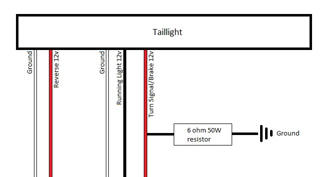
Have to bump this thread to ask a question ... I am planning on installing resistors on my stock DF taillights to eliminate my rapid blinker issue. From Torch's last post in this thread, it sounds like the correct way to do this is to wire a resistor in parallel between the +12v turn signal/brake wire and ground. Something like this (sorry for the terrible Paint skills!):
Just want to confirm!
Just want to confirm!
Torchandregdoc
Goblin Guru
The wiring is correct, but I can't confirm the resistance until I look at the car tomorrow.Have to bump this thread to ask a question ... I am planning on installing resistors on my stock DF taillights to eliminate my rapid blinker issue. From Torch's last post in this thread, it sounds like the correct way to do this is to wire a resistor in parallel between the +12v turn signal/brake wire and ground. Something like this (sorry for the terrible Paint skills!):
View attachment 20452
Just want to confirm!
Torchandregdoc
Goblin Guru
We used 25's

 dfkitcar.com
Jim McDonald // Extended Track // '09 HHR SS/TC Automatic
Nice mod! Are those train horns going to find their way into the build?
Towerdog
Goblin Guru
So I have a few questions to add.
Headlights, I followed the factory wiring colors to save confusion but man am I confused. I assume that the Blue and white on the right side and the blue and yellow on the left are the low and high beam wires but when energized with just low beam both wires have power. Turn the high beams on and I loose power to one on each side (backwards from what it should be)
I have no power to the wires that are for the mirror turn signals.
Tail lights work as I wired them (2 separate cubes per side) but the reverse lights (light green wires) are energized all the time no matter whether it is in reverse or not. Have unplugged the sensor with no change.
And why can I turn on the lights w the key out of the ignition and I have to turn them to off to get them to shut off?
Zoom Zoom
Goblin Guru
Head lights should cut off after a few minutesSo I have a few questions to add.
Headlights, I followed the factory wiring colors to save confusion but man am I confused. I assume that the Blue and white on the right side and the blue and yellow on the left are the low and high beam wires but when energized with just low beam both wires have power. Turn the high beams on and I loose power to one on each side (backwards from what it should be)
I have no power to the wires that are for the mirror turn signals.
Tail lights work as I wired them (2 separate cubes per side) but the reverse lights (light green wires) are energized all the time no matter whether it is in reverse or not. Have unplugged the sensor with no change.
And why can I turn on the lights w the key out of the ignition and I have to turn them to off to get them to shut off?
Towerdog
Goblin Guru
So I have figured out the turn signal/high beam situation.....
The real head scratcher is the reverse lights. They are on constantly, there is continuity between the backup switch plug and everything.. and here's were it gets interesting, if I unplug the fuse in #25 spot on the BCM (ECM/TCM) the lights go to half lit. Makes no sense those wires did not get spliced.
The real head scratcher is the reverse lights. They are on constantly, there is continuity between the backup switch plug and everything.. and here's were it gets interesting, if I unplug the fuse in #25 spot on the BCM (ECM/TCM) the lights go to half lit. Makes no sense those wires did not get spliced.
Last edited:
Ross
Goblin Guru
Sounds like a ground issue. You might be powering the circuit thru another circuit.So I have figured out the turn signal/high beam situation.....
The real head scratcher is the reverse lights. They are on constantly, there is continuity between the backup switch plug and the light wires.. and here's were it gets interesting, if I unplug the fuse in #25 spot on the BCM (ECM/TCM) the lights go to half lit. Makes no sense those wires did not get spliced.
Towerdog
Goblin Guru
Looking that way... I edited the above the LT Green on the backup switch plug has continuity with everything!Sounds like a ground issue. You might be powering the circuit thru another circuit.
Towerdog
Goblin Guru
Ok this gets weirder the further I go.
Found the issue with the reverse lights being powered by the ECU/TCU fuse,, There are two identical plugs on the engine harness and I had them swapped. But now I have the drivers side tail/brake light working as it should the cube next to it has the running/tail light on and the reverse light on. Moving on to the next light being a tail/reverse,,, Tail light on as it should. Passenger tail/brake light has the tail light on dim. Drivers side only the turn/brake works the passenger neither work.
When the plugs were reversed aside from the reverse lights being on everything worked as it should!
SmsDetroit
Goblin Guru
Do you still have some of those resistors?I'll do my best to help you, but this may be a case of the blind leading the blind.
I wouldn't classify this as a "taillight hack". I think what is going on here is, the powered CHMSL wire carries a load while the ignition is on, and the ECM expects to see a certain resistance load on that wire, presented by the stock CHMSL. To be clear here, I think the CHMSL is designed to add resistance to the circuit and ground it, so not just a normal "light bulb" so to speak. I got the 100-ohm number from a thread on here, but I wasn't confident it was right, so I grabbed a 100-ohm resistor and tested it.
Without any resistance load on the light blue wire, it was carrying 7.5v anytime the ignition was on (Tested via 20v setting on my multimeter, touching the positive probe to the light blue wire and the negative probe to ground). Then I shaved some of the jacket off the light blue wire, connected the 100-ohm resistor to that bare spot, and ran the other end of the resistor to ground. Then I again tested with the 20v setting on my multimeter, and at the end of the light blue wire (as in, AHEAD of the resistor in the circuit, not after it), I saw the more-expected outcome: nearly 0v without the brake pedal applied, and a full 12v with the pedal applied.
So in other words, I think there's logic in the ECM that tests for a load on the CHMSL power wire, and that the stock CHMSL provides somewhere around 100 ohms of resistance. Since the ECM "sees" the resistance, it functions normally (enables cruise control and sends the proper voltage through the CHMSL wire). I do NOT feel that the resistor is changing the voltage on the wire via electrical formula, or however you want to say it. I hope that makes sense.
I used the formula I did above, because we don't know the current (amps) going through the wire. It can't be much, but we don't know it, nonetheless. You can find the Power by squaring the Voltage, then dividing that by the Resistance. So 12 volts squared, over 100 ohms. 144/100 = 1.44W, so you would need a resistor that can handle that plus a little more. Since I suspect the resistor I used to test was not rated for that much, I ordered some 2-watt, 100-ohm resistors off Amazon. I'll only need one, and a pack of 100 of them is incoming, so I'd be happy to send you one via snail mail if you want it.
As for the brake lights being on while in gear ... how do they behave when you're NOT in gear?
Ark :D
Goblin Guru
Yes, but I got a bigger one with a heatsink on it because the little one got HOT. You'll want to do the same.Do you still have some of those resistors?
SmsDetroit
Goblin Guru
Can you please share which one you got?Yes, but I got a bigger one with a heatsink on it because the little one got HOT. You'll want to do the same.
Ark :D
Goblin Guru
uxcell 25W 100 Ohm 5% Aluminum Housing Resistor Screw Tap Chassis Mounted Aluminum Case Wirewound Resistor Load Resistors Gold Tone 2 pcs: Amazon.com: Industrial & Scientific
uxcell 25W 100 Ohm 5% Aluminum Housing Resistor Screw Tap Chassis Mounted Aluminum Case Wirewound Resistor Load Resistors Gold Tone 2 pcs: Amazon.com: Industrial & Scientific
www.amazon.com
Towerdog
Goblin Guru
These are the ones I bought. I put one on the 3rd brk light and two up front on the flasher wire to the mirrors to slow the rate of blink down.uxcell 25W 100 Ohm 5% Aluminum Housing Resistor Screw Tap Chassis Mounted Aluminum Case Wirewound Resistor Load Resistors Gold Tone 2 pcs: Amazon.com: Industrial & Scientific
uxcell 25W 100 Ohm 5% Aluminum Housing Resistor Screw Tap Chassis Mounted Aluminum Case Wirewound Resistor Load Resistors Gold Tone 2 pcs: Amazon.com: Industrial & Scientificwww.amazon.com