No crank problem
- Thread starter 25074
- Start date
Scott #321
Well-Known Member
I believe 06 has the same plug for the brake and clutch switch. These are easy to connect to the wrong connector resulting in the described condition. Just thinking out loud here for some possibilities.
Mahkoi
Well-Known Member
I ran into an issue where I had power at all the right places and ground was showing in the right places but the car would not crank. I had a layer of paint between the starter and the block so starter was showing it was grounded when it poked it w/ the power probe but not grounded enough to carry a current. Not sure if this applies to you but maybe will help someone who like myself should know better but ambition and bud light got the better of them.
Ark :D
Goblin Guru
I had similar problems with my build, and the issue ended up being a pin in one of my engine fuse block connectors. I ended up having to reshape one/a few of those pins to make good contact with the underside of the fuse box. Took like 20 pages of electrical troubleshooting, calls from Lonny, and PM's from many of the good people of this forum, to pin it down.
Don't be defeated, you'll get through it, I promise.
Don't be defeated, you'll get through it, I promise.
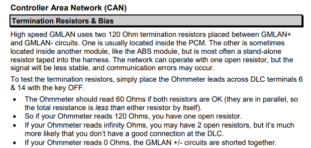
Just to confirm that is zero resistance (continuity from pin to pin) not open circuit? Zero resistance would indicate that the GMLAN circuit is shorted together. Each leg should go out with two 120ohm resistors connecting each leg together. Maybe someone can describe the path for your model or supply the wiring diagram.
25074
Member
Should there be continuity through ALL of the tan data wires?
And should there be continuity through ALL of the tan/black data wires?
I’m looking at a schematic and it looks like there would be 3 different sets of data wires going to different things.
i would think there should be continuity between each of them independently?
And should there be continuity through ALL of the tan/black data wires?
I’m looking at a schematic and it looks like there would be 3 different sets of data wires going to different things.
i would think there should be continuity between each of them independently?
Your path is probably similar to this one
Build Guide Part 10 - Thinning the Body Harness | DF Kit Car Forum
All of the tan/black should connect together and all of the tan wires should connect together.
I probably miss used continuity in my previous post. You will have continuity across the two pins but with 60ohms resistance. If the previous link matches your wiring, start disconnecting the individual modules, starting with the pcm, until you no longer get zero resistance. This should narrow it down to what section of wires is shorted.
Ross
Goblin Guru
Some meters do a flashing 0 if there is no connectivity.I checked resistance between pin 6 and 14 on the obd and got 0
now what?
If you connect the meter's leads together does it display 0 too?
My meter will usually show 0.2 or 0.4 ohms with the leads touching.
If you truly have 0 ohms, then you have a short in your GM high speed LAN wires.
To track down where the short is, you could disconnect the power steering LAN wires, and check the resistance across the 2 LAN tan wires, then check resistance across the 2 LAN brown wires.
Keep tracing down the wiring diagram, until you find where the short is.
Here is the GM LAN wiring points for my 2006 SS SC donor... after I thinned the wires.
The PCM should have 120 ohms resistance, and I'm not sure where the other 120 ohm resistor is... maybe the power steering box.
All of the wiring diagrams I have found do show the second 120ohm resistor in the power steering.
If you start at the power steering end tracking down the short, then make sure you reconnect the connectors as you check each on, assuming you continue reading at the data link connector.
If you start at the power steering end tracking down the short, then make sure you reconnect the connectors as you check each on, assuming you continue reading at the data link connector.
Dale E
Well-Known Member
Hello all Goblineers. I wanted to throw this into the history of this and the process of diagnosing. (If you don't give the doctor the full history he sometimes misses the real cause of illness -- so this is history not shared with all. Hope 25074 doesn't mind me interjecting this outcome) I had a couple of PM's with @25074 I asked him to ground the front left starter relay spayed. This is his response to doing that.
" so he (his son) went to the garage while I was getting ready for work and he ran a ground wire like you said and the engine cranked even with the key in the run position.
I was able to get it to sort of run…we must have cracked the fuel like when we switched them to the other side so it was running really bad and I shut it off.
So we are getting closer.
he was able to find a video that said that the starting is controlled by the computer and that it might be those stupid data wires.
thoughts???
why would it start in the “run” position ?"
I think I remember reading that he had taped the clutch switch??
Hope this helps you all get him sorted out on this issue!! You all have the power and resources which I don't have!!
Dale
Yes we might be running down a different problem with the data wires, although he has a problem there also. Some of the info in the first post is confusing. Youtube has ruined trouble shooting skills since people try to look up symptoms to find the solution. That's why I had him checking power at relays first since it sounded like he was getting a start signal to the start relay.
The path highlighted in my link in post 31 isn't correct since we don't use the EBCM but it probably is the right diagram to use as a base.
Ross, are you sure of your colors in your link in #32? I've never seen a diagram that has anything but the tan/blk and tan wires for the High Speed GMLAN.
Ross, are you sure of your colors in your link in #32? I've never seen a diagram that has anything but the tan/blk and tan wires for the High Speed GMLAN.
Ross
Goblin Guru
Well, we have different donors, so maybe something changed. I'm sure my 2006 SS SC has brown wires and tan wires for the GM high speed LAN.The path highlighted in my link in post 31 isn't correct since we don't use the EBCM but it probably is the right diagram to use as a base.
Ross, are you sure of your colors in your link in #32? I've never seen a diagram that has anything but the tan/blk and tan wires for the High Speed GMLAN.
Sluggonaut
Goblin Guru
Same colors on my 07 SS/SC.Well, we have different donors, so maybe something changed. I'm sure my 2006 SS SC has brown wires and tan wires for the GM high speed LAN.
Corgithulhu
Well-Known Member
Figured I'd throw in a thing to check that I haven't seen yet - If you suspect the anti-theft is monkeying with your start, make sure you have the 10A fuse for the "HVAC/PK3" in place and not blown - for me it was position 10 on the BCM that would be in your passenger foot well. For whatever reason, that fuse happens to send 12 volts to the anti-theft module at the key. I referenced a diagram for a 2006 SC model, but I doubt that part of the car is different (worth checking if you have your model's specific wiring diagram). Without it in place, the car won't fire up because the anti-theft isn't getting power.
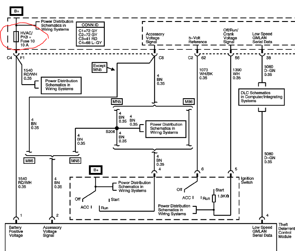
After reading through, not sure if that's really where your problem is, but I was definitely having issues that sounded like yours while I had that fuse out. I was using it to power something else that was critical, and I thought HVAC was a good fuse to take.
After reading through, not sure if that's really where your problem is, but I was definitely having issues that sounded like yours while I had that fuse out. I was using it to power something else that was critical, and I thought HVAC was a good fuse to take.