Corgithulhu
Well-Known Member
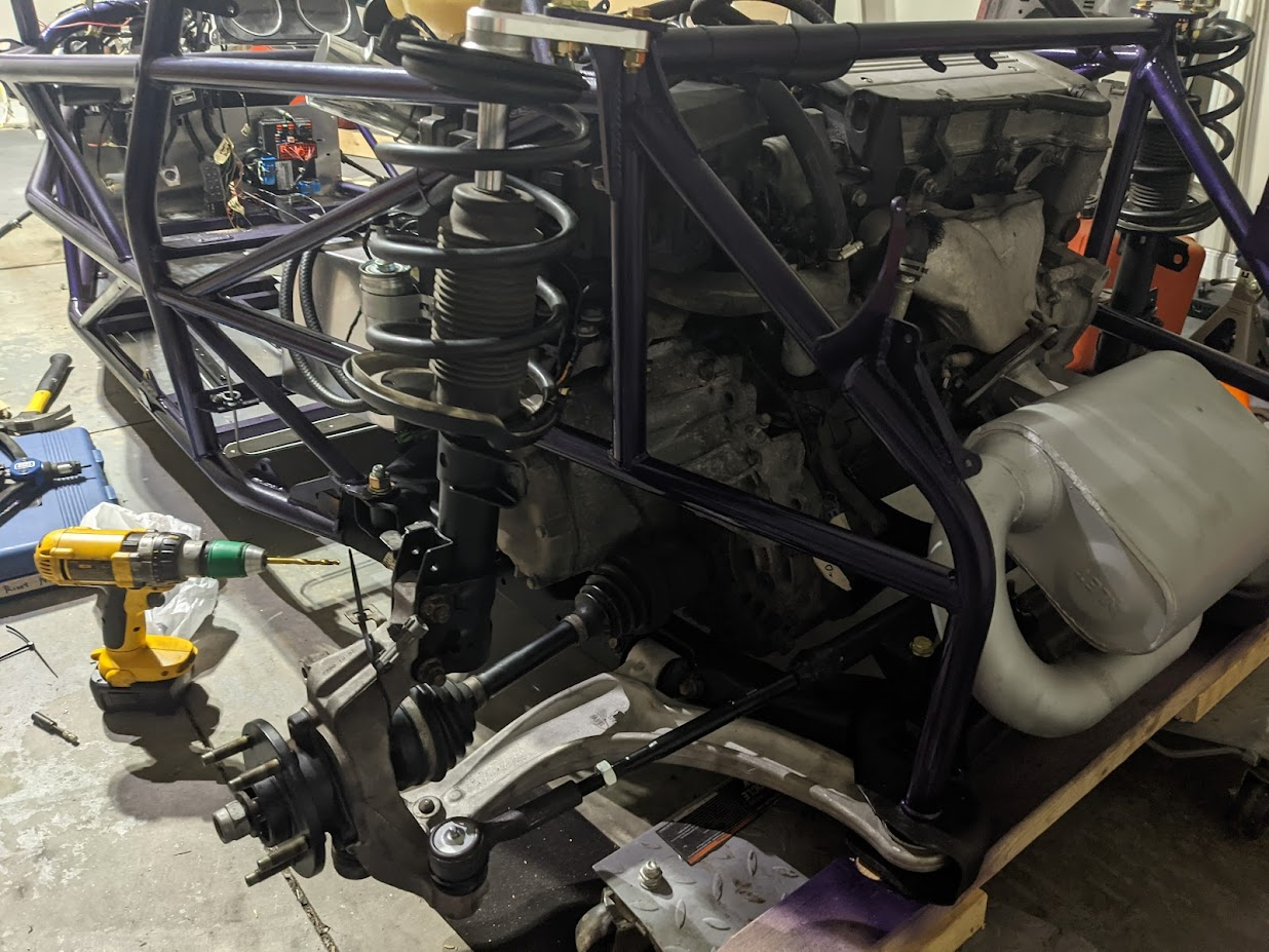
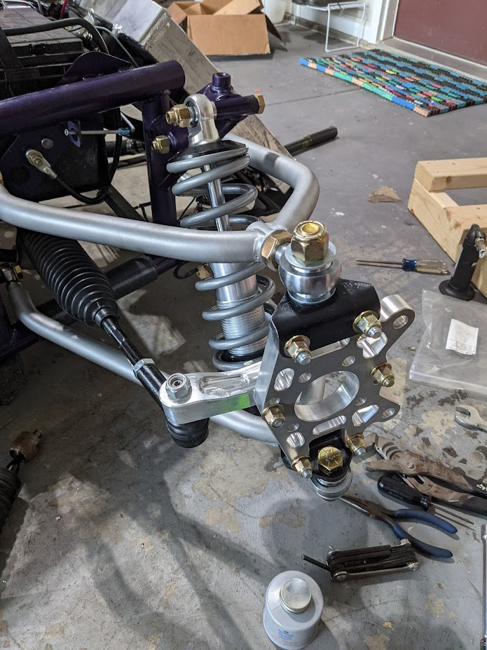
Some more progress being made every night. Rear suspension is mostly together. Front is coming together, but I found out I don't own a 15/16" wrench to torque the big upright bolts so that's where I sit until I go get one.
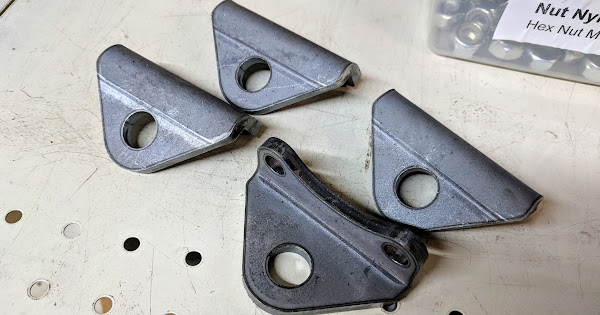
That rivet nut tool is no fun right now. I think I strained a ligament in my left arm when I put the floors on, and I can barely do two before I make my arm a useless lump for four hours. Project rivet nut is officially on hold until my feeble 32 year old body finds time to recover.
That rivet nut tool is no fun right now. I think I strained a ligament in my left arm when I put the floors on, and I can barely do two before I make my arm a useless lump for four hours. Project rivet nut is officially on hold until my feeble 32 year old body finds time to recover.
 I think I want to use a bunch of them and the Factory Five kit I have my eyes on uses a lot of them too.