OptimizePrime's Build | '10 SS/TC #168 | Registered

OptimizePrime

Goblin Guru
OK now that I have these electrical issues out of the way, let's rewind and catch up to speed.

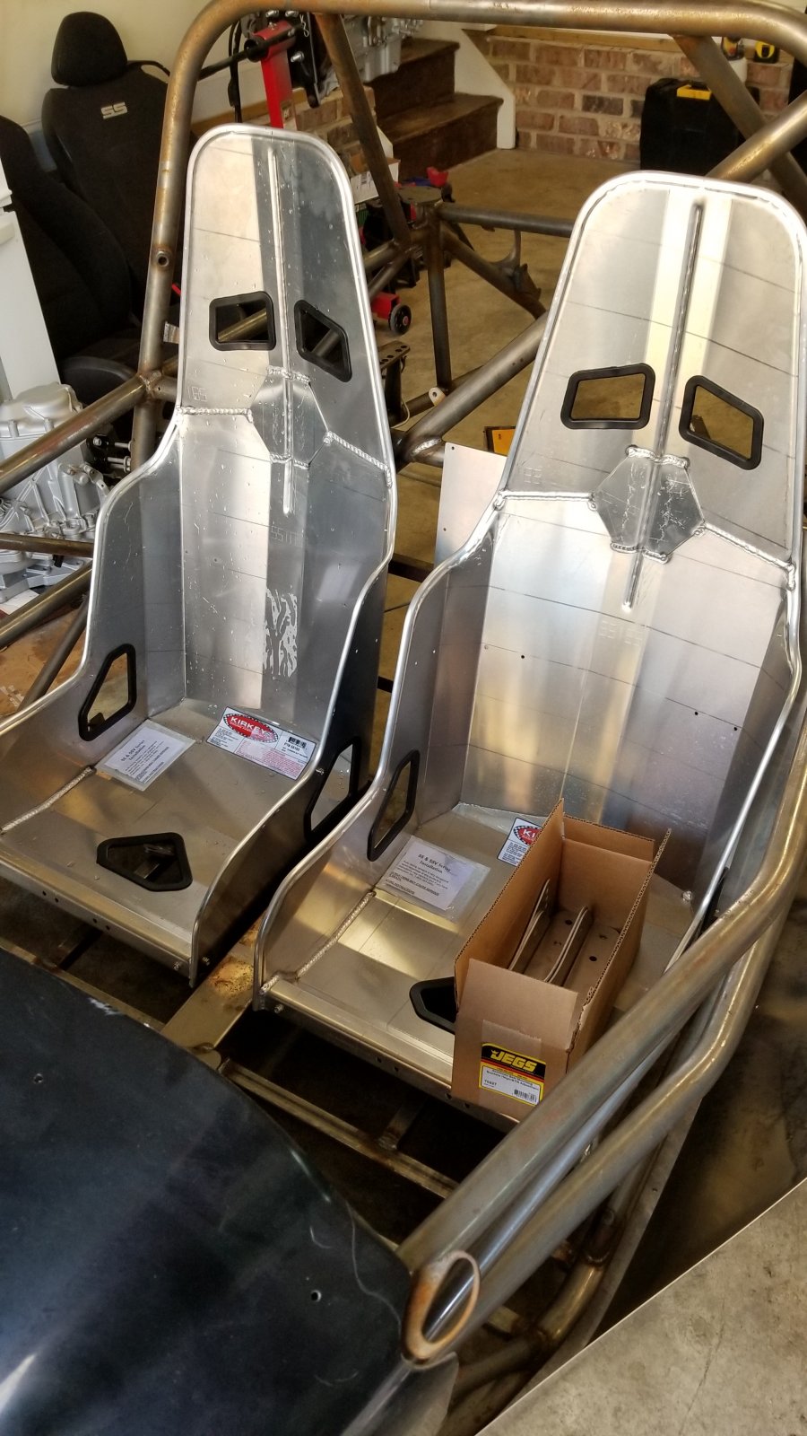
From the beginning I knew I didn't want to reuse the stock seats, and I'm too much of a masochist to purchase the DF Corbeau seat brackets to make life easy. What that meant is that I effectively had to think around the seats first as it would require welding the frame and adjusting the steering column which basically meant I'm going manual steering which then means I need to think around the dash and where the turn signals and other controls would go... it's a headache - just get the DF seat brackets and call it a day. Here's the build up

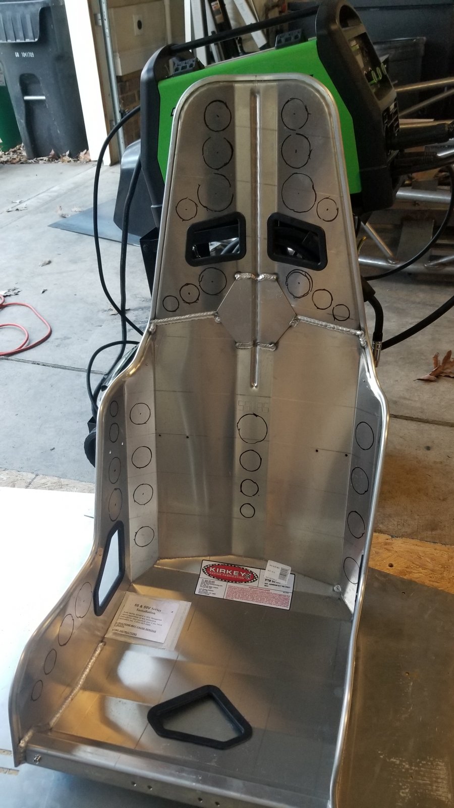
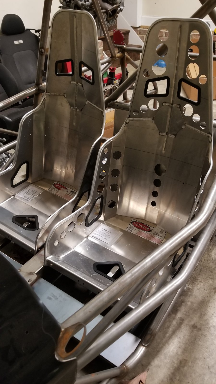
I went with Kirkey 18.5" Pro Street Drag seats with Jegs brackets. I'm 6'2 205ish and they're quite wide (but not too wide) without padding and fit the space perfectly. The lines of the seat oddly line up with the lines of the frame too so that's an added bonus. I quickly went to town turning them into basically a bomber seat - I still want to dimple the holes but they're odd sizes so I'm designing a solution that'll work (more to come on that)
11701

11702

11703


Using 24" aircraft rails for the mounts themselves. Using these rails allowed for semi-adjustable seating while still being safe. The aircraft rails are aluminum and needed support. Welded in some 2"x1" 1/8" channel and she's rock solid now.
11705


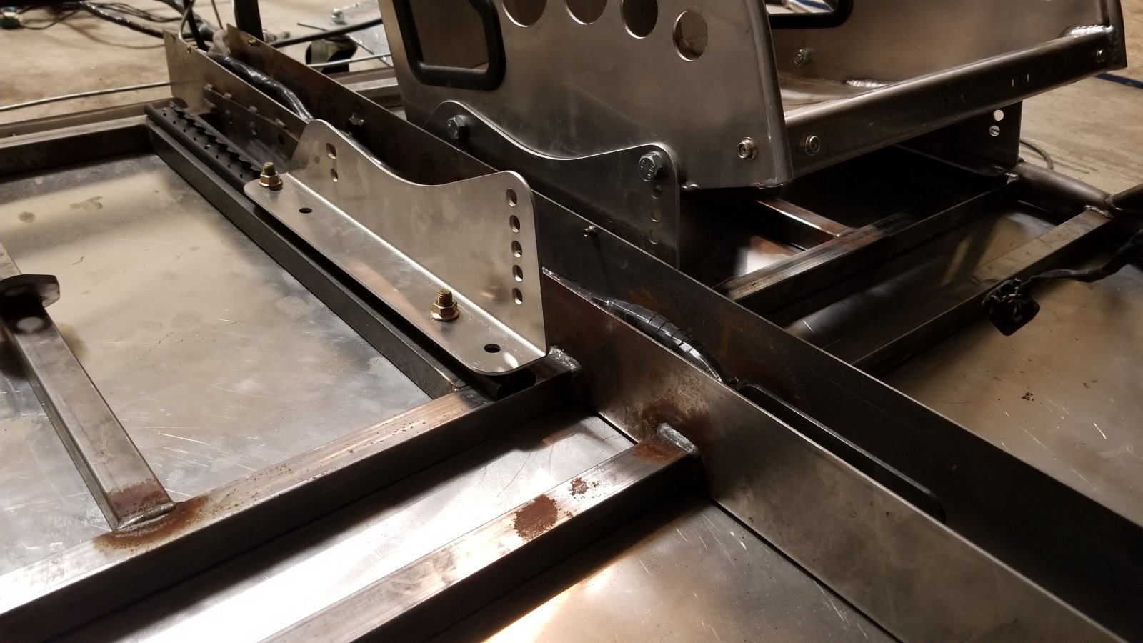
Tight clearances through here boys
11706


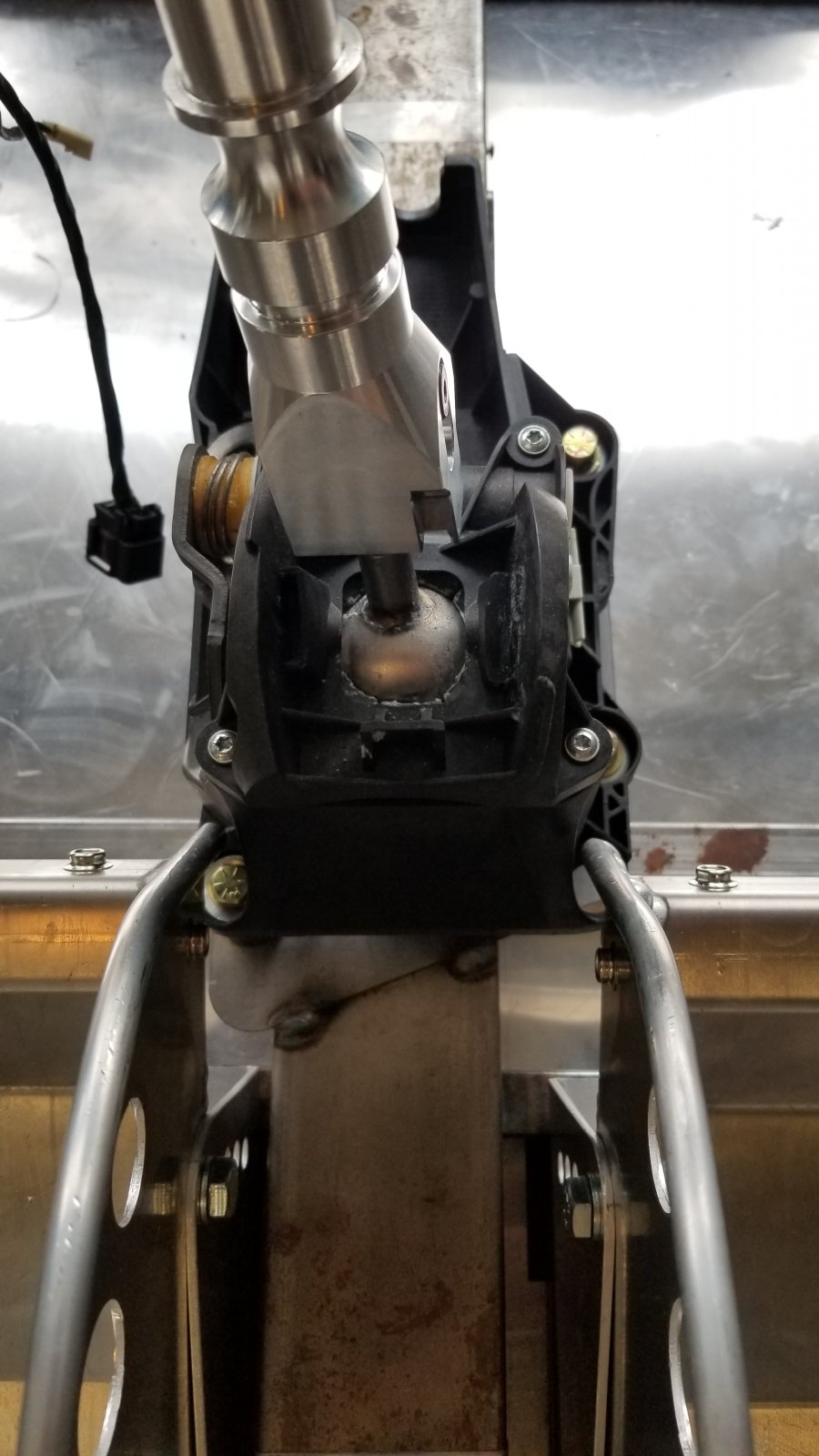
Next up, full manual steering rack
 
Last edited:

OptimizePrime

Goblin Guru
OK so, seats are basically done but I wanted this thing to feel like an F1 car where everything is just right there - the stock power steering was too high, too far away, and oddly offset compared to the seats (although it didn't feel goofy while sitting in it). In reading some other opinions on the ps I thought the manual rack is the way to go. I took some notes from Ken on his manual rack and just decided to wing it ...what's the worst that could happen

Offset
11707

11708


Purchased a 36" rod, a u-joint, and a 4.5" drop, quick release, wheel hub adapter to go from 3bolt to whatever it is and wheel and cot dayum did it clean up this area. I'm a big fan of this full carbon fiber steering wheel - I went this route as opposed to alcontera mainly due to wear. I'm going to jump in this thing and whip it around town and I don't want to have to put on gloves or worry about the weather.

11709

11710

11711


Quick release and my porous welds - cut the rod about 8" or so and welded up the quick release
11712

11713


At this point, I'll deal with the loss of turn signals and buttons later
 
Last edited:

OptimizePrime

Goblin Guru
Were you planning to have a hand brake? The space between the seats looks tight!
Yep! I picked up the e-brake package. The channel itself should be wide enough to get things to work, if not I'll pick something up aftermarket. I haven't crossed this path yet so fingers crossed here.
 

OptimizePrime

Goblin Guru
The seats and steering where quite the self-imposed headache, I wanted to take a sec to address some more typical headaches you'll find along the build phase.

First, the TC fuel pump orientation. I've created a how-to here (http://dfkitcar.com/forum/index.php?threads/turbo-fuel-pump-orientation.785/post-26901) - if you don't do this the gas gauge will never read correctly.

Second, I took my clutch and pressure plate off and didn't have the clutch alignment tool when I went to throw it back on. When you have a 3D printer, this type of thing is annoying to spend money on and wait for it - so I printed out a clutch alignment tool and it worked flawlessly. STL attached.
11715


Third, the ABS sensor plug for the front hubs needs to go. When this plug is removed (via a dremel / chipping it off) the guts are now open to the elements and a simple cap is required. I've attached the STL for this also
11716

11717


Fourth, the rear rotor hub diameter is ever so slightly larger than the hub itself. The rotor needs a ring to center it on the hub. No Pic but it's straight forward. STL attached

Fifth, I highly suggest the solid motor mounts for this build. I don't have any silicone or tape between my panels and at idle the vibration is hardly noticeable and rattles are not even audible. You will have some heartburn installing the mount closest to the gas tank. I highly recommend not unbolting the upper motor mounts, what's easier is to loosen the undercarriage bolts with the rear solid motor mount attached and then get the two bolts threaded in > lift the undercarriage with a jack and torque the undercarriage bolts in > then torque the stubborn solid mount --- super easy this way for me.
11719


Sixth and final (for now), the Goblin supplied TC transmission cable bracket will cause binding and / or full lockout of certain gears (probably 5th and reverse). You have to come up with a solution to straighten out the cable - mine was welding in a 1/8" spacer on both sides to get her close enough.

Kinky
11720


11721


Straight-Edge
11722
 

Attachments

OptimizePrime

Goblin Guru
Moving on, before I took the donor apart I purchased an OTTP short throw shifter with solid mounts / clamps. Well, the shifter and mounts were great but the clamps themselves will not work with the DF supplied rod. Reason being, the diameter of the DF rod is much smaller than the OTTP clamp and it's too large of a gap to overcome safely with some light jerry rigging. I was also trying not to use the stock parts because the black cobalt plastic piece this rod inserts into is notorious for breaking (the goonsquad broke there's live on one of their youtube vids). Also, the way the DF rod installs has reverse threaded nuts and it's just too fiddly to deal with.

I cut the stock Cobalt shift rod with the correct OTTP diameter and welded her on to the DF supplied rod so the rod ends would work as expected. this also enabled the same flexibility for adjustment with far less fiddleyness
11724


11725


After I got the motor in the next hurdle was thinking around the intercooler. Personally I didn't really like the idea of the A2W setup as it wasn't as efficient, introduced more room for leaks / faults, was more expensive than a FMIC, more of a hassle to work around and wasn't as visually pleasing. I was going to hang the FMIC off the two uprights and went about copying some of the other board members with their FMIC purchases. In all of my excitement, I purchased the a FMIC where the core size matched the others, but the total size was much larger....yay

Oddly enough, this actually worked to my advantage with regards to mounting options. Mounting the FMIC in this position gave me enough space to see underneath it (for a rearview mirror at some point) and cleanly route the plumping. <Task failed successfully>
11727


11728


11729


Some of you may notice the catch-can mounted to the light post. Here's the routing which lines up with the stock lines. The filter off the intake pipe is one directional.
11756
 
Last edited:

OptimizePrime

Goblin Guru
I was reading a few of the other members not completely happy with their brake pedal feel so they picked up a regulator. I printed out a bracket and installed her. In driving the car, the brakes are still a bit scary mainly because they engage at the bottom and it's quick - I can lock up the tires pretty easily.I need to dial in this regulator and maybe reduce the size of the vacuum tubes for less pedal travel before they engage. I may need to bleed the brakes better too. STL attached for those who want it.

Paying the cat tax
11731


11732


Next challenge was the brake lights. I'm far too cheap to pay for the Rigid Chase lights, instead I poured countless hours trying to get some cheaper lights to work lol In hindsight, I still really dig these directional turn signals but lord was it a headache to get these to work correctly - vid coming soon. I started another thread on the headaches (here: https://dfkitcar.com/forum/index.php?threads/led-headlight-turn-signal-brake-wiring.1563/ ) associated, but this is what she looks like

Designing and printing the brackets were a lot of fun for this. I started the Goblin build with no 3D Printing experience and it's gratifying to create something from scratch that looks and functions well.

11734


11735


Next up were the sideview mirrors. I felt the DF mirrors looked too much like ears, even more so with circular headlights. The design of the lights in the housing also didn't really fit the direction I was trying to go with this. Going to different mirrors required an alternate mounting solution. I finally settled on cutting off the DF mounts and welding a nut onto a steel plate and welding that on. These mirrors are much more low profile - to be determined on how long they last in the path of rocks and other debris.
11736


As we get closer to street time, I picked up the Takata Drift III belts and was not let down. I like the idea of the typical seatbelt style latch for ease of use.
11737


Here are a few teasers before officially calling this phase complete. Still need the wing, exhaust, polish off the dash / dash wiring. I'm still on the fence about adding the side panels. Enjoy!
11738

11739
 

Attachments

Last edited:

KSLunsfo

Well-Known Member
Some of you may notice the catch-can mounted to the light post. I removed the stock tubes, kept the PCV, routed them together and plumbed it to the turbo.
What is the line on the turbo side (or non crank case side) of your catch can setup connecting to? Is it connecting to a pressurized portion of the turbo system by chance, such as into the intake track?
 

OptimizePrime

Goblin Guru
What is the line on the turbo side (or non crank case side) of your catch can setup connecting to? Is it connecting to a pressurized portion of the turbo system by chance, such as into the intake track?
If I'm reading you correctly, the photo under the paragraph may help answer this one? The line coming out of the catch-can routes to the turbo inlet tube you were asking about in another thread.

I'm basically merging the pcv line that was once connecting to the top of the intake with the one that was feeding to the turbo inlet. Both were pre-turbo so in theory there's no difference?

Does this help?
 
Last edited:

KSLunsfo

Well-Known Member
If I'm reading you correctly, the photo under the paragraph may help answer this one? The line coming out of the catch-can routes to the turbo inlet tube you were asking about in another thread.

I'm basically merging the pcv line that was once connecting to the top of the intake with the one that was feeding to the turbo inlet. Both were pre-turbo so in theory there's no difference?
I may just not be able to perfectly make out exactly where the lines are running, and also can't visualize the ecotec engines like I can the DSM as I'm not exactly experienced with the ecotecs. Typically, the PCV is between the valve cover and intake manifold as I'm sure you know. I imagine you know what you're doing, but just thought I'd point it out in case you're setup to pressurize your crank case. I would hate for you to have to rip the drivetrain out after your first time in boost to replace a rear main. Right now your PCV is T'd into a line that goes back into the VC, making the PCV useless. Again, if I'm seeing it correctly.
 

OptimizePrime

Goblin Guru
I may just not be able to perfectly make out exactly where the lines are running, and also can't visualize the ecotec engines like I can the DSM as I'm not exactly experienced with the ecotecs. Typically, the PCV is between the valve cover and intake manifold as I'm sure you know. I imagine you know what you're doing, but just thought I'd point it out in case you're setup to pressurize your crank case. I would hate for you to have to rip the drivetrain out after your first time in boost to replace a rear main. Right now your PCV is T'd into a line that goes back into the VC, making the PCV useless. Again, if I'm seeing it correctly.
Ah, okay I got you. From what I've read, there's actually two PCV's on the TC. One is external (from valve cover to intake pipe which is pre-turbo, can be seen in my pics above) and one is located inside the intake manifold between the runners which is post-turbo. I believe the PCV you're referencing is the internal one, which I kept stock as it was too much work for what's effectively a band-aid that (maybe) marginally helps (one catch-can was the least I could do). I thought the money/time/effort was better spent on meth injection and/or just blasting the valves every 50k miles.
 

JBINTX

Goblin Guru
I was reading a few of the other members not completely happy with their brake pedal feel so they picked up a regulator. I printed out a bracket and installed her. In driving the car, the brakes are still a bit scary mainly because they engage at the bottom and it's quick - I can lock up the tires pretty easily.I need to dial in this regulator and maybe reduce the size of the vacuum tubes for less pedal travel before they engage. I may need to bleed the brakes better too. STL attached for those who want it.

Paying the cat tax
View attachment 11731

View attachment 11732

Next challenge was the brake lights. I'm far too cheap to pay for the Rigid Chase lights, instead I poured countless hours trying to get some cheaper lights to work lol In hindsight, I still really dig these directional turn signals but lord was it a headache to get these to work correctly - vid coming soon. I started another thread on the headaches (here: https://dfkitcar.com/forum/index.php?threads/led-headlight-turn-signal-brake-wiring.1563/ ) associated, but this is what she looks like

Designing and printing the brackets were a lot of fun for this. I started the Goblin build with no 3D Printing experience and it's gratifying to create something from scratch that looks and functions well.

View attachment 11734

View attachment 11735

Next up were the sideview mirrors. I felt the DF mirrors looked too much like ears, even more so with circular headlights. The design of the lights in the housing also didn't really fit the direction I was trying to go with this. Going to different mirrors required an alternate mounting solution. I finally settled on cutting off the DF mounts and welding a nut onto a steel plate and welding that on. These mirrors are much more low profile - to be determined on how long they last in the path of rocks and other debris.
View attachment 11736

As we get closer to street time, I picked up the Takata Drift III belts and was not let down. I like the idea of the typical seatbelt style latch for ease of use.
View attachment 11737

Here are a few teasers before officially calling this phase complete. Still need the wing, exhaust, polish off the dash / dash wiring. I'm still on the fence about adding the side panels. Enjoy!
View attachment 11738
View attachment 11739
has anyone actually run a Goblin with no side panels? Seems like a good recipe for getting a leg beat up by rocks. Although the added ventilation would be a plus for sure!
 

KSLunsfo

Well-Known Member
Ooo, perhaps I've learned something! After looking at my engine again (turbo still attached) I see that the line from the turbo goes directly to the vc, just can't make sense of what that's doing. If it's connected to the pressurized portion of the compressor housing, then why would it go to the vc at all, as you could never have negative pressure there to pull from the crank case...? Hmm, I need to research this more. Maybe as I tear further into it things will make more sense. I'm wanting to do a nice catch can system myself, so I'll want to understand it all better.
 

OptimizePrime

Goblin Guru
Ooo, perhaps I've learned something! After looking at my engine again (turbo still attached) I see that the line from the turbo goes directly to the vc, just can't make sense of what that's doing. If it's connected to the pressurized portion of the compressor housing, then why would it go to the vc at all, as you could never have negative pressure there to pull from the crank case...? Hmm, I need to research this more. Maybe as I tear further into it things will make more sense. I'm wanting to do a nice catch can system myself, so I'll want to understand it all better.
If you take your intake off and look at the turbo inlet you'll see it's just before the wheel with likely a fair amount of oil around it. If you want to replace the intake manifold PCV, your only option is to drill out the intake mani to remove the PCV and stick a barb in > route that to an external PCV > catch-can > back to intake manifold. There's also the powell racing separator for $400ish which tries to do the same thing. In a nutshell, even with all this stuff you can't get around the coking.

edit: while doing research if you come up with anything please update! this may help (https://www.chevyhhr.net/forums/2-0l-performance-tech-46/installing-oil-catch-can-54350/ ) - and after reading this I may have it setup incorrectly. Lots of differing opinions on this btw
 
Last edited:

KSLunsfo

Well-Known Member
edit: while doing research if you come up with anything please update! this may help (https://www.chevyhhr.net/forums/2-0l-performance-tech-46/installing-oil-catch-can-54350/ ) - and after reading this I may have it setup incorrectly. Lots of differing opinions on this btw
I found that same post last night and was coming to post it! It appears as there's no check valve in his valve cover correct? Surely they wouldn't design a PCV valve above the baffling of the valve cover, that would be terrible to have to replace a valve cover because of a PCV. Port 1 connects to pathways that run farther down into the crank case and Port 2 comes in above the valve cover baffling. So, it looks to me like you can get rid of that check valve altogether since internally, ports 1 and 2 are connected. Does that sound right to you? I think he's adding to the confusion a bit by calling them PCV ports, they're really just venting ports.

Sorry we've gone down a rabbit hole on your build thread, the build is looking awesome!
 

OptimizePrime

Goblin Guru
I found that same post last night and was coming to post it! It appears as there's no check valve in his valve cover correct? Port 1 connects to pathways that run farther down into the crank case and Port 2 comes in above the valve cover baffling. So, it looks to me like you can get rid of that check valve altogether since internally, ports 1 and 2 are connected. Does that sound right to you?

Sorry we've gone down a rabbit hole on your build thread, the build is looking awesome!
Not at all brotha I really appreciate the question, it's given me a reason to revisit and look at it in more detail. The way I have it now, with the VC barbs T'd > catch-can > turbo is actually incorrect. I'll fix my setup and take a pic and update - long story short it looks like we need to put a barb onto the DF intake pipe to route Port #1 with the check-valve in place as Port #1 is intaking metered fresh air and Port #2 is pushing 'dirty' air. So, on my setup now Port #1 is just taking in dirty air.

What's interesting is the intake barb is not accounted for by DF so I don't know how other TC builds have this setup correctly (that is without just putting a small filter on port #1 which is introducing unmetered air).

More to come - thanks again!
 

George

Goblin Guru
I do not run and crank case ventilation through my engine Have two dash ten hoses connected to valve cover.
Also blocked and welded the crankcase vent valve in cylinder head. Do not like oil in my head exchanger as it becomes an insulator. The dash ten hoses are fitted into the the front and rear portions of the valve cover. Dip stick does not popup any move when at high rpm and boost.

Brad
 

KSLunsfo

Well-Known Member
I do not run and crank case ventilation through my engine Have two dash ten hoses connected to valve cover.
This is essentially how I have my turbo eclipse set up, 2 -10AN lines coming off the valve cover running through catch cans. Assuming the lines come in above the baffling this is the best location to vent the crank case, it's far as possible from oil and will still prevent any crank case pressure build up.
 

OptimizePrime

Goblin Guru
After further review, I reverted back to the stock routing for the vacuum / vc lines. The catch-can is now introduced for just Port #2. Here's the flow

I originally T'd the lines together, the fault in this idea is the middle barb (Port 1) would be intaking 'dirty' air from Port #2. Whether it makes a material functional difference I don't know, but felt it was easy enough to fix.
11758


Stock routing with the catch-can introduced for Port #2 only. Port #1 is now taking in metered fresh air (as opposed to just putting a filter on the barb or drawing from Port #2). All hoses are 3/8" fuel hose which is closest to stock (this matters)
11759
 
Top