Please Help Turn Signal Wiring Diagram and Diagram Decoding

viperbmw69

Active Member
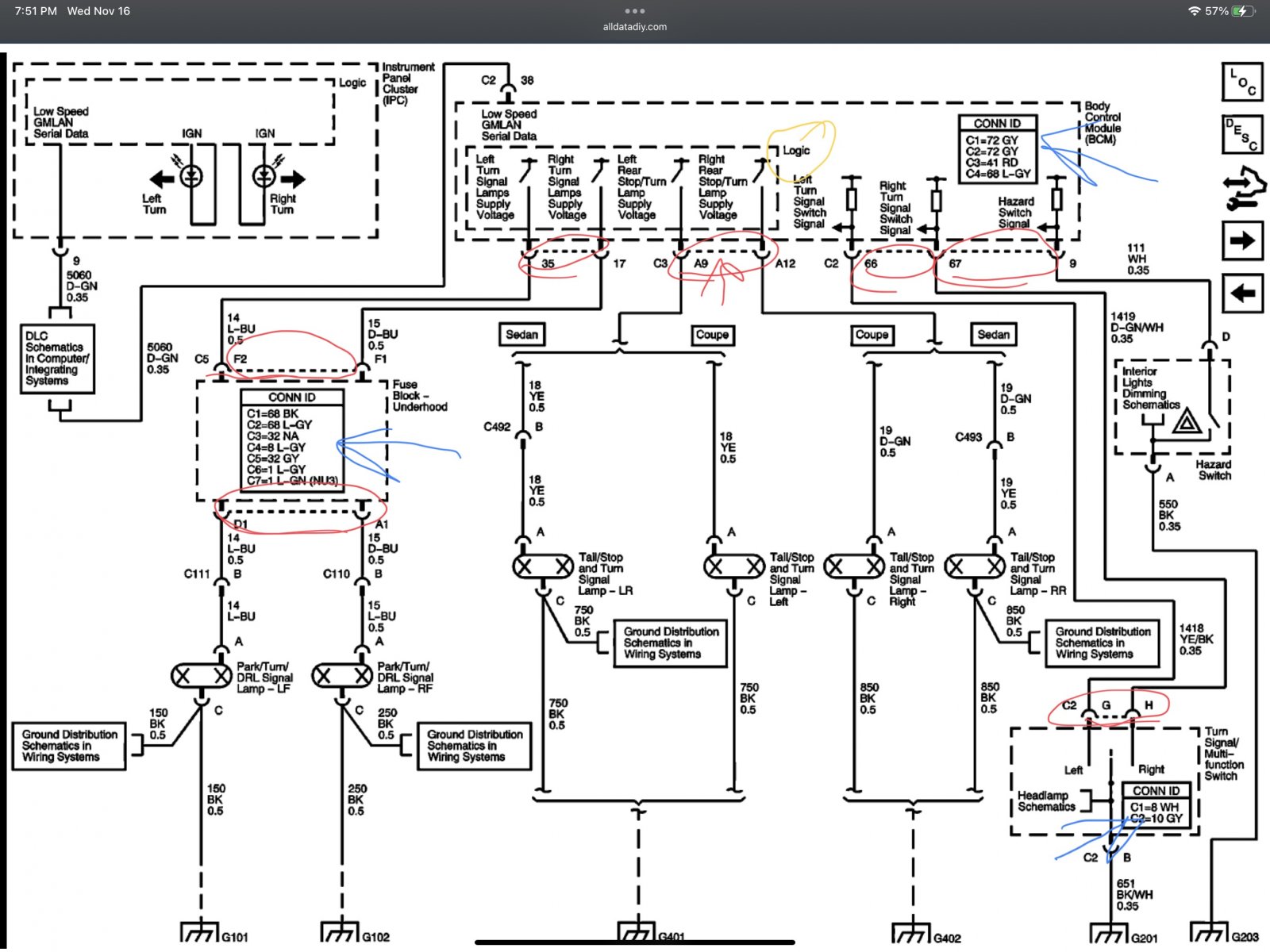
Can someone help me read the OE wiring diagrams? I did my own harness but I am having issues with the Turn signal wiring. I am not really. understanding the Alldata diagrams. Such as the one attached. I am not understanding the symbols and numbers. The box that says CONN ID does not make sense to me. I see the Plugs as J1 and J2 on the BCM. Somehow I guess the plugs are called X1 and X2 on the schematics? Im so confused......

The connectors that are connected with dotted lines mean what???

How should I read the CONN ID boxes?

What does the "Logic" part mean?

The Red is the Connectors??
The Yellow is the Logic I dont understand
Blue is the CONN ID box i'm talking about.

IF ANYONE CAN HELP ME BY SENDING ME A SIMPLE DIAGRAM FOR "ONLY" TURN SIGNAL WIRES THAT WOULD HELP ME :)
FCBBF211-5AD2-42B7-A8EF-889A822C7FBF.jpeg
 

Ross

Goblin Guru
Conn ID = Connector identification
C1 is a 72 pin grey connector.
C2 same,
C3 41 pin red connector.
37036

37037


The dotted lines are wires that are all on the same connector. One of the wires will mention the connector, eg: C1.
Logic just means there is a computer inside, that has some programming logic to it.
Your blue arrow just tells you about the 7 connectors on the fuse box.
37038
 
Last edited:

Ross

Goblin Guru
Your questions are good ones. Many people are intimidated by the wiring diagrams.
I don't think there is a forum thread on explaining the AllData wiring information.
So this will serve as the first one. I am now including a AllData header in my images, so people can see where I got it from on AllDataDIY. Some of this info is hard to find on AllData, and I use the search function a lot.

The more I look at the AllData wiring, the more I learn about it.
The connectors are sometimes referred to as C1, X1 or J1. The first letter doesn't seem to be consistent, but the connector number does.
 

viperbmw69

Active Member
Your questions are good ones. Many people are intimidated by the wiring diagrams.
I don't think there is a forum thread on explaining the AllData wiring information.
So this will serve as the first one. I am now including a AllData header in my images, so people can see where I got it from on AllDataDIY. Some of this info is hard to find on AllData, and I use the search function a lot.

The more I look at the AllData wiring, the more I learn about it.
The connectors are sometimes referred to as C1, X1 or J1. The first letter doesn't seem to be consistent, but the connector number does.

I can not thank you enough for the login info for alldata!!! Huge help

Can you help me understand the turn signal connections?

From what I understand the front turn signals go through the Fuse Box? and the rear do NOT go through the fuse box? that would seem ok for a cobalt but with the fuse box in the rear do we flip them using the DF wiring videos?
 

Ross

Goblin Guru
You can't flip them, as the goblin needs the stop lights at the rear.
I used the wires in the blue box for the rear tail lights, because they have stop, running and turn signals combined.
The green box is for the front turn signals, as they have both turn and running lights combined.

37039


PS: if you plan on flat towing your goblin, you connect the trailer electrical plug to the wires in the blue box too. Then the tow vehicle will use the goblin tail lights, even with the key off.
 
Last edited:

viperbmw69

Active Member
You can't flip them, as the goblin needs the stop lights at the rear.
I used the wires in the blue box for the rear tail lights, because they have stop, running and turn signals combined.
The green box is for the front turn signals, as they have both turn and running lights combined.

View attachment 37039

PS: if you plan on flat towing your goblin, you connect the trailer electrical plug to the wires in the blue box too. Then the tow vehicle will use the goblin tail lights, even with the key off.

Ok so how about this...

Where should the turn wire for the front mirror ends go? So if I test from the Left and Right front turn signal ends the Right one does not work when the turn switch is pointed Right....
The Left turn wire does get fluctuated voltage when the switch is turned Left.
The rear turn signal wires on both sides is not getting any voltage when the turn switch is turned either way.....
 

Ross

Goblin Guru
Are you running LED lights?
LED lights only work when the + and - are in the right direction. Filament light bulbs don't care which wire is + or -.

If you test the wires on your lights with a 9V or 12V battery, you will figure out which wires are used, which are + and -.

Or you can search the forum, as there are multiple posts about wiring various lights.
 
Last edited:

Sluggonaut

Goblin Guru
Are you running LED lights?
LED lights only work when the + and - are in the right direction. Filament light bulbs don't care which wire is + or -.

If you test the wires on your lights with a 9V or 12V battery, you will figure out which wires are used, which are + and -.
I had this problem with my Amazon 3rd brake light. It didn't work until I connected its black wire to positive and red to ground. Felt very strange to do that.
 

baustin

Well-Known Member
Wire colors for what they typically get used for varies all around the world, it's especially fun when touching designs from APAC and EMEA regions and adapting them for US use... This is true for car style 12VDC as well as 240/400/480/600VAC. Multimeters are your friend and I definitely used a small 12VDC battery to confirm the orientation on my lights before wiring.

amazon link to A23 batteries that are 12VDC and smaller than AA batteries
 

Goblinfanclub1234

Well-Known Member
if anyone wants to see how "goofy" my wiring is check out these diagrams I made up. pretty straight forward though. I moved the front turn signals into the headlights since I have integrated turn signals in mine. used cheapo waterproof amazon pre-wired connectors. (load resistors not shown here)

37048
 
Last edited:
Top