Keckster
Well-Known Member
As I was waiting on my kit to be delivered I dove into different upgrades I wanted to make along the way. I've seen murmurs of resetting the odometer on the goblin to keep better track of your mileage. Plus who wants their brand new sports car to say it has 100K+ miles... This guide is not intended to be used for anything other than a goblin build and I highly recommend you check your state rules and regulations before attempting. With all that said, let's get started.
Before we get started you will need some external hardware in order to reprogram the EEprom chipset that stores the odometer reading.
-You will need an EEprom CH341a reader/writer like these: EEprom Reader/Writer
-You will also need a test clip to connect to the clip like this: Test Clip
Step 1: The first step obviously is to get your BCM out of the goblin/Cobalt and break that bad boy open! This process is semi destructive when taking the cover off so make sure you are absolutely sure you want to proceed. Once you are sure you are willing to take on this procedure you must proceed to remove all relays, fuses, and connectors from the BCM.
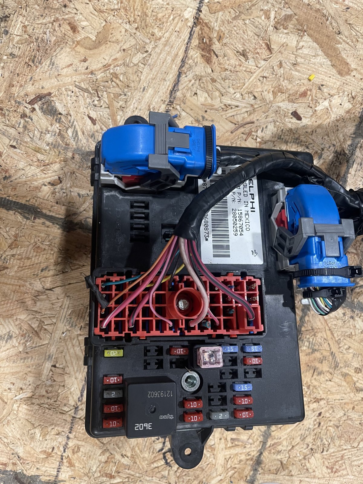
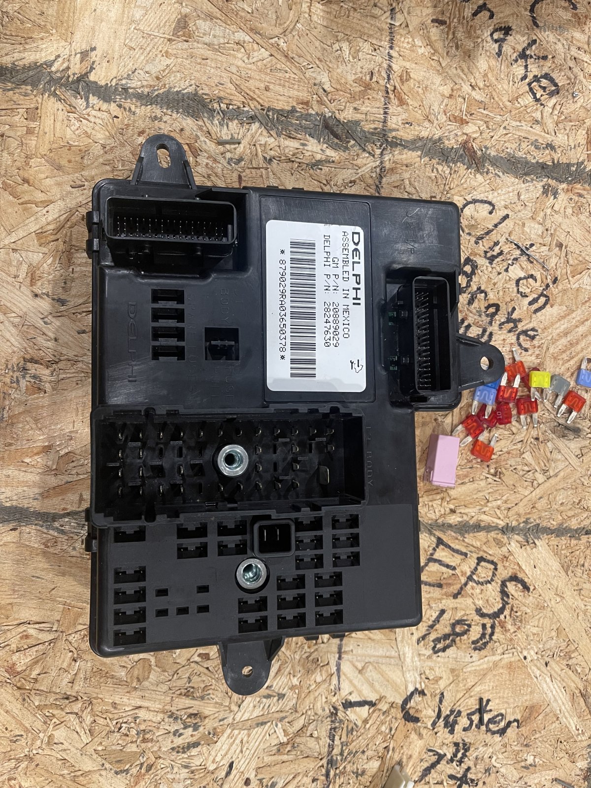
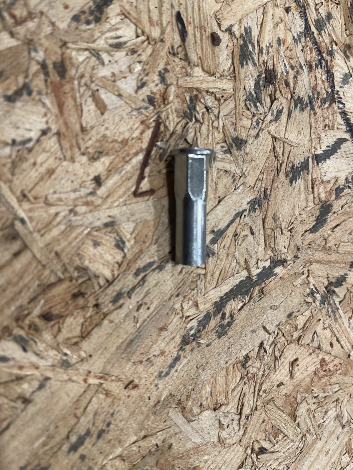
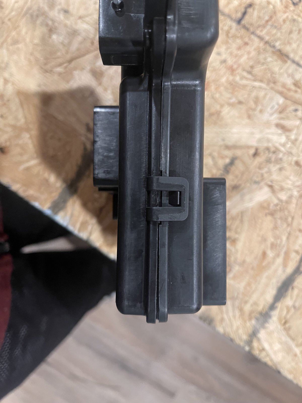
Step 2: Once all attached devices are removed from the BCM this is where the destructive part comes in... As we can see the BCM has two metal threaded pieces to hold our large Red and Grey BCM connectors in. One side of these threaded pieces is flat while the other is flared. We will be drilling out the flared end until these threaded inserts just fall out easily. I used a 5/16 drill bit and slowly and carefully drilled out the threaded insert. Upon removal I sanded the end of these inserts to remove any burrs. now that our biggest obstacle is removed we can just pry each of the plastic clips on the edges to easily open up our BCM.
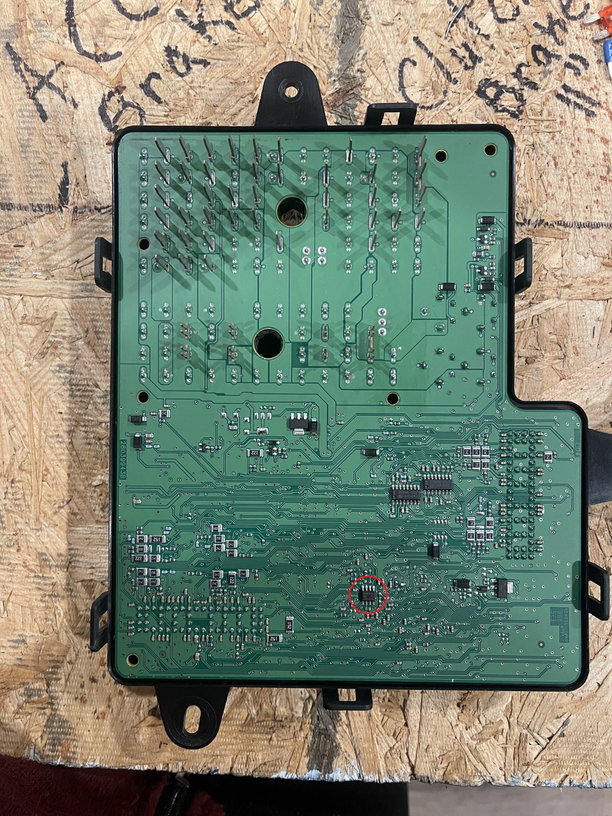
Step3: Locating the EEprom Chipset (Circled in Red). The Chip we are searching for is located slightly to the right of center on the bottom of our BCM.
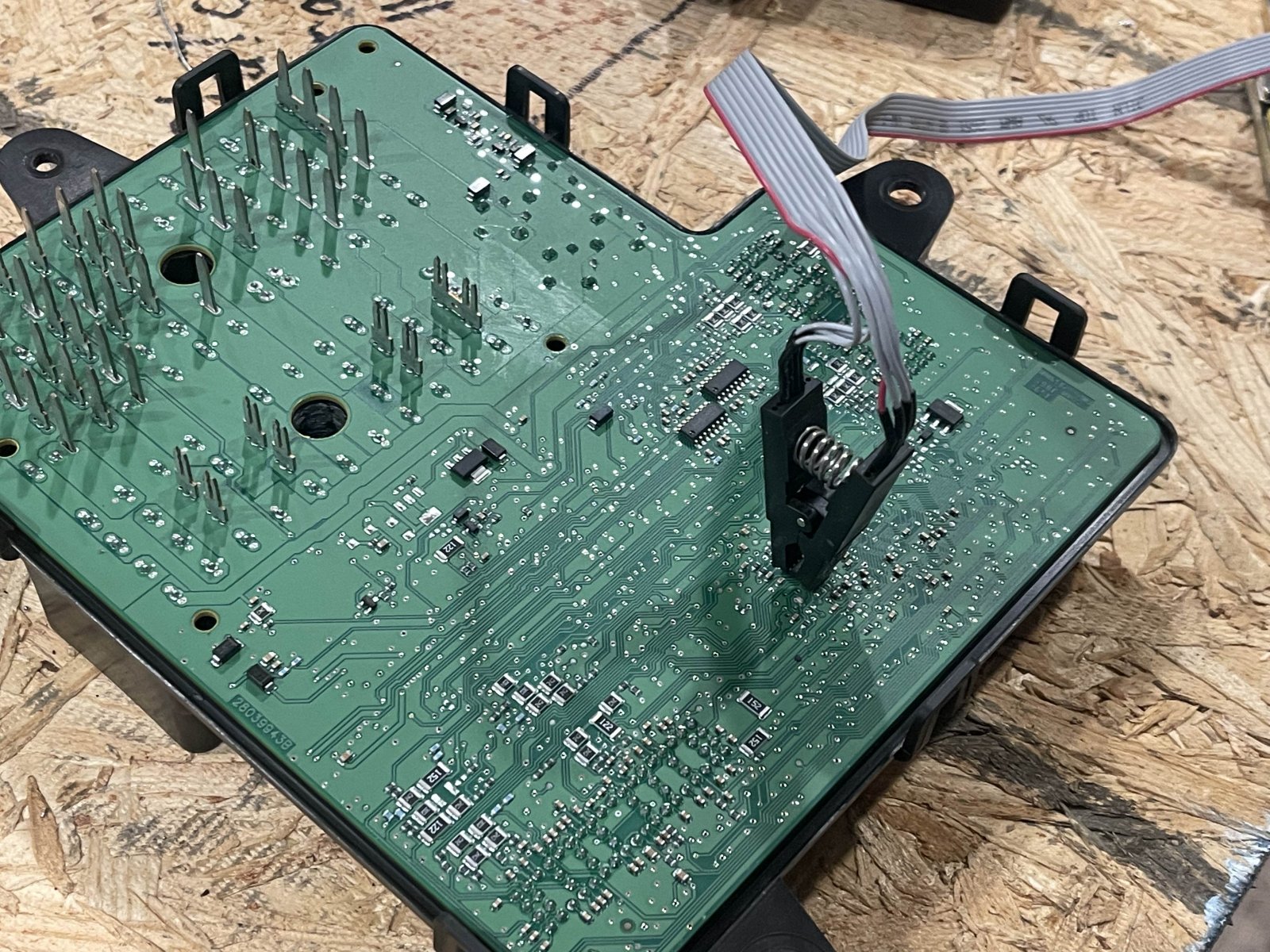
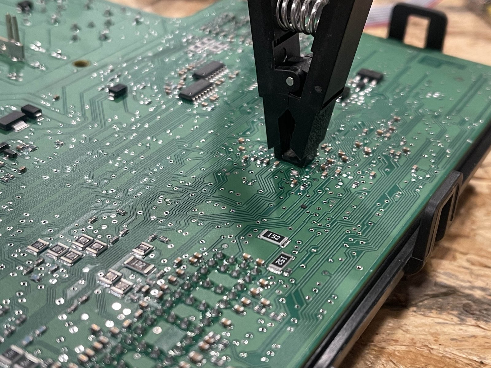
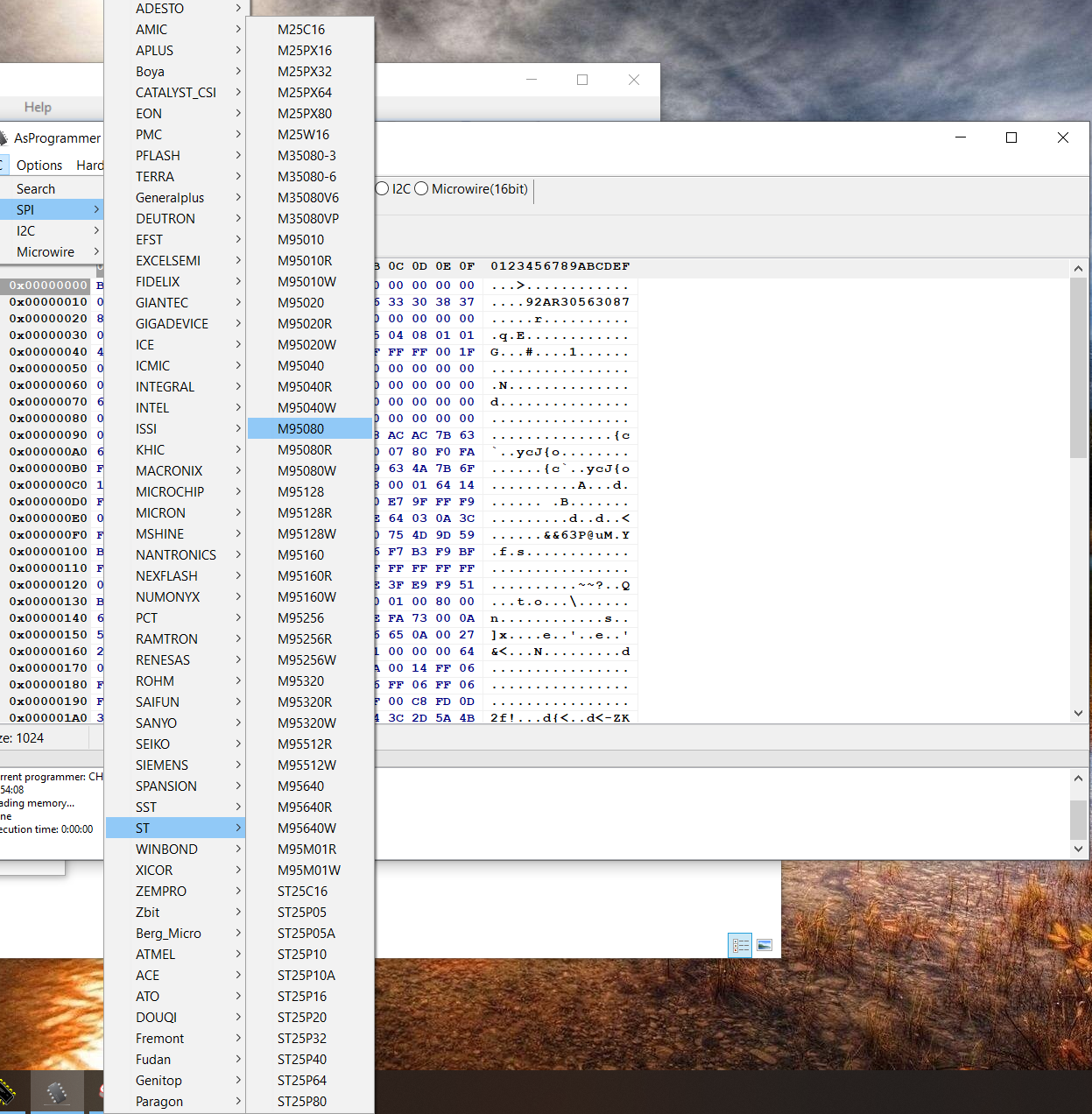
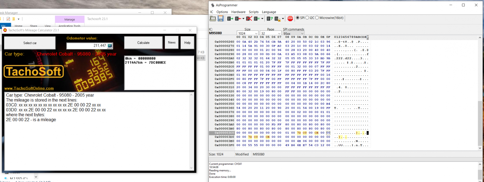
Step4: Next thing is to connect to the chip using the test clip. I use a program called ASprogrammer to read and program my chip. Once connected to our chip we must setup our programmer by setting the chipset type (IC>SPI>ST>M95080). Once the chipset is selected click the read icon. You will know your chip was read properly when the second line on the right shows the last 12 numbers of the serial number on your BCM are the same with every pair flipped.
Note: the chipset is very small and hard to get the clip on correctly so it may take a few attempts before you are able to read or write to it... Also make sure to try flipping the clip in case your orientation is incorrect.
Step 5: Now that we have successfully read our chip we can proceed to update our mileage. Using a program called Tachosoft I was able to choose a mileage to set on our BCM. Once you select your vehicle, enter the desired mileage, and hit calculate Tachosoft will tell you what to change in ASprogrammer. For my example I had to change the positions highlighted in yellow to all zeros to reset the odometer completely as my car is not on the road yet.
Step 6: Upon changing your values and clicking the program button you can slap your BCM back together and reinstall it in your goblin! The rear red BCM connector should pull against the now lose threaded insert and has no chance of falling out but the grey one could slide out even when threaded in. You can use some glue to hold the insert in just make sure nothing gets inside the BCM housing.
I am not a tech pro but I know my way around most gadgets so if anyone has questions I will answer to the best of my ability.
Before we get started you will need some external hardware in order to reprogram the EEprom chipset that stores the odometer reading.
-You will need an EEprom CH341a reader/writer like these: EEprom Reader/Writer
-You will also need a test clip to connect to the clip like this: Test Clip
Step 1: The first step obviously is to get your BCM out of the goblin/Cobalt and break that bad boy open! This process is semi destructive when taking the cover off so make sure you are absolutely sure you want to proceed. Once you are sure you are willing to take on this procedure you must proceed to remove all relays, fuses, and connectors from the BCM.
Step 2: Once all attached devices are removed from the BCM this is where the destructive part comes in... As we can see the BCM has two metal threaded pieces to hold our large Red and Grey BCM connectors in. One side of these threaded pieces is flat while the other is flared. We will be drilling out the flared end until these threaded inserts just fall out easily. I used a 5/16 drill bit and slowly and carefully drilled out the threaded insert. Upon removal I sanded the end of these inserts to remove any burrs. now that our biggest obstacle is removed we can just pry each of the plastic clips on the edges to easily open up our BCM.
Step3: Locating the EEprom Chipset (Circled in Red). The Chip we are searching for is located slightly to the right of center on the bottom of our BCM.
Step4: Next thing is to connect to the chip using the test clip. I use a program called ASprogrammer to read and program my chip. Once connected to our chip we must setup our programmer by setting the chipset type (IC>SPI>ST>M95080). Once the chipset is selected click the read icon. You will know your chip was read properly when the second line on the right shows the last 12 numbers of the serial number on your BCM are the same with every pair flipped.
Note: the chipset is very small and hard to get the clip on correctly so it may take a few attempts before you are able to read or write to it... Also make sure to try flipping the clip in case your orientation is incorrect.
Step 5: Now that we have successfully read our chip we can proceed to update our mileage. Using a program called Tachosoft I was able to choose a mileage to set on our BCM. Once you select your vehicle, enter the desired mileage, and hit calculate Tachosoft will tell you what to change in ASprogrammer. For my example I had to change the positions highlighted in yellow to all zeros to reset the odometer completely as my car is not on the road yet.
Step 6: Upon changing your values and clicking the program button you can slap your BCM back together and reinstall it in your goblin! The rear red BCM connector should pull against the now lose threaded insert and has no chance of falling out but the grey one could slide out even when threaded in. You can use some glue to hold the insert in just make sure nothing gets inside the BCM housing.
I am not a tech pro but I know my way around most gadgets so if anyone has questions I will answer to the best of my ability.
Attachments
-
 388.3 KB Views: 223
