Ross's extended city, easy entry Goblin- 06 SS/SC, NW Arkansas
- Thread starter Ross
- Start date
Rttoys
Goblin Guru
Yep, been there, done that. I busted up my race bike last year. It sucks, but it happens.I can relate.
Glad it's not worse and he's okay.
Ross
Goblin Guru
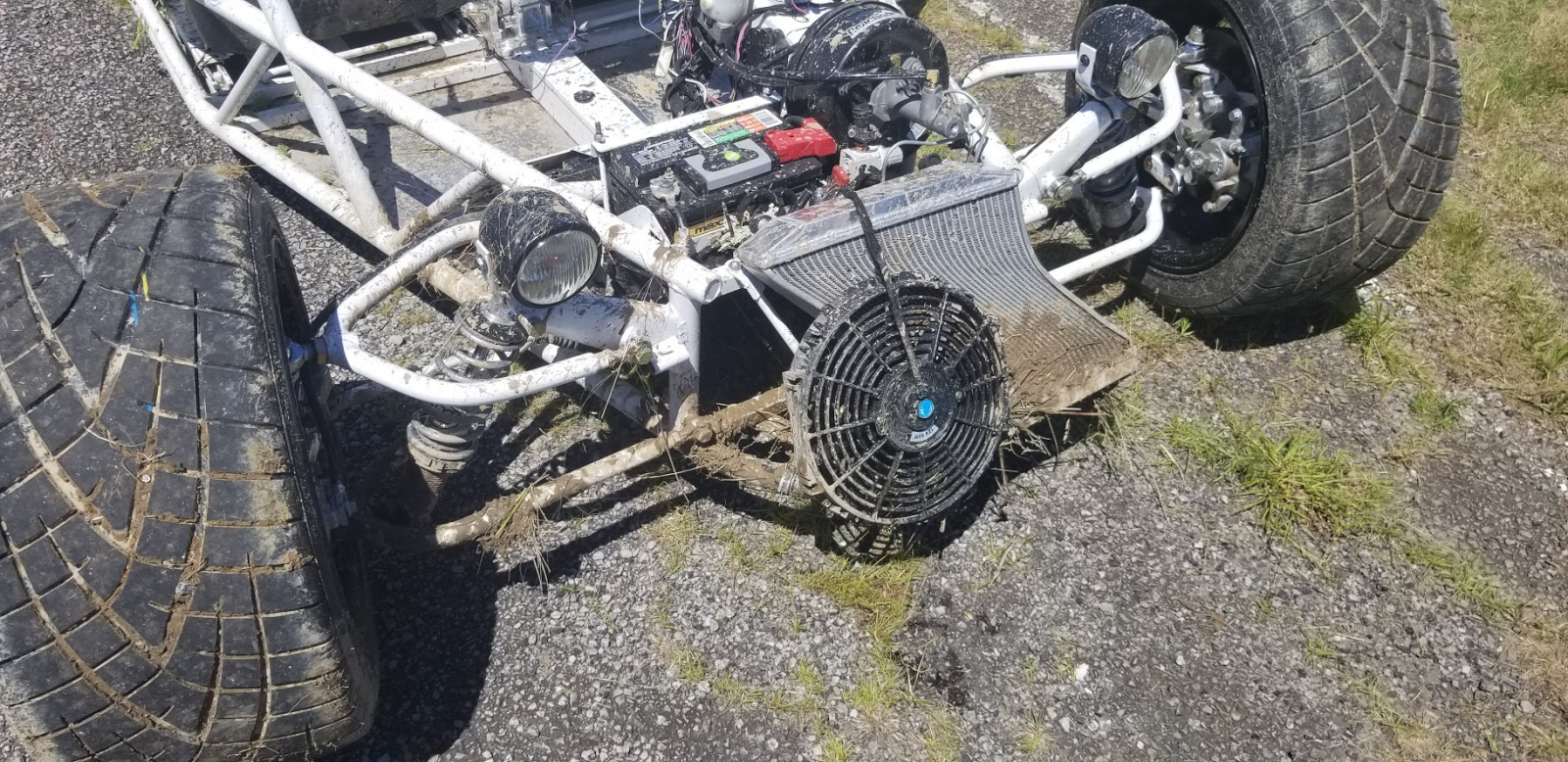
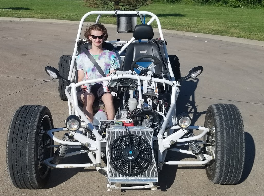
Before and after pictures. 24 hours.
The radiator got a diagonal squeeze in the press, and it holds water and pressure. The radiator support got untwisted some too.
He seems happy that it holds pressure. We took it out for a test drive to make sure there wasn't any other surprises like a wheel alignment issue.
I still need new parts, but these would work in a pinch. Need to put the good tires back on. 2020 Midwest meet is on!
Waterdriver
Goblin Guru
Nice job, looks good!
That radiator is a lot more resilient that I had thought.
That radiator is a lot more resilient that I had thought.
Karter2026
Goblin Guru
You missed some mud with the pressure washer.Before and after pictures. 24 hours.
The radiator got a diagonal squeeze in the press, and it holds water and pressure. The radiator support got untwisted some too.
He seems happy that it holds pressure. We took it out for a test drive to make sure there wasn't any other surprises like a wheel alignment issue.
I still need new parts, but these would work in a pinch. Need to put the good tires back on. 2020 Midwest meet is on!
View attachment 14385 View attachment 14386
 Cup holders you need cup holders for him!
Ross
Goblin Guru
Yeah, it got a long pressure wash. Ian said when he hit the mud at the bottom "There was a wall of mud in the air, then I went thru it".You missed some mud with the pressure washer.
I pulled 30 pounds of mud out from under the radiator, 20 more pounds from the rear wheel.
I does need another wash... lol
Ross
Goblin Guru
Took the Goblin out 15.7 miles for supper today. Did a MAF tune on the way there, and another 15.7 mile tune on the way home.
Just giving the Goblin a shake down run before the Midwest spring meet. The new header, and exhaust gaskets that don't leak, have made minor changes to the tune. The engine actually got up to 200F in the heat of the day, but the trip home after dark, it was back to 170F.
Just giving the Goblin a shake down run before the Midwest spring meet. The new header, and exhaust gaskets that don't leak, have made minor changes to the tune. The engine actually got up to 200F in the heat of the day, but the trip home after dark, it was back to 170F.
Ross
Goblin Guru
I have been having an issue with the dash gauges dropping to zero, and the starter motor not working when the gauges don't work.You are correct, the Cobalt uses differential CANbus and a proprietary single ended CANbus, both of which are forms of serial networks. When speaking about the CANbus in question, there is no circuitry isolating one segment of wire from another in the Cobalt - GM just chose to pass the CANbus "in and out" of each module to add complication with little if any up-side. You can most certainly measure the resistance end to end as it is just a "Wire". There are vehicles that do isolate network segments into broadcast domains using gateway modules. -the Cobalt is not one.
Background:
Differential CANbus is simply a parallel network architecture that uses a bus topology. The normal layout is each module taps into the bus with two wires. GM decided to actually pass the wiring through the various modules. If you use a meter, you will see there is a dead short between the in and out of each CANbus lead on all the modules. This implementation has little advantage and many disadvantages.
You can choose to re-arrange the network layout or even abandon the "in and out" method used by GM all together and the bus will still work. Ideally you still want to maintain a network where you have a terminating resistor at the beginning and end of the network. In the case of the Cobalt, the terminating resistors are in the PSCM and the ECM. The diagnostic connector does not have any active electronics so it does not count, and the only other module the Goblin uses is the BCM and in some cases, the RPD. So these two modules need to ideally stay in the middle of the network.
Bold below indicates a module with a terminating resistor.
DLC<--->PSCM<--->(RPD)<--->BCM<--->ECM
Being an intermittent problem makes it harder to find the issue.
Can I just run an extra twisted pair from the ECM to the PSCM, and thereby making a 2 ways the electricity can get each module?
Briann1177
Goblin Guru
I could be wrong, but I'm pretty sure there is something in the BCM that can "speak" to both the high speed and low speed networks. I only say this because the cluster data like RPM comes from the low speed network. There is no direct connection that I'm aware for the low speed network and the ECM. So I believe the only way to traverse the networks so to speak is through some kind of "proxy" device inside the BCM.
Briann1177
Goblin Guru
Not sure what this might mean for your gauge cluster issues.

 dfkitcar.com
Fozda's Standard Track Goblin - 06' SS/SC #196
Aaaaand end of Day 3! Should be pretty darn close to done, aside from the missing parts, by the end of the day tomorrow!
Ross
Goblin Guru
Brian, since I have a similar problem to Ark, I am following your directions for my 2006 LSJ.Do these things in the fuse box without any cranking:
1. Pull the crank relay.
2. There should be one pin that is connected directly to ground and should read < 5 ohms.
3. There should be another pin that probably won't be a dead short, but should maybe be like 200 ohms to ground. This would be the purple wire.
4. There should be one pin that constantly has 12V on it.
5. Once you have those three pins mapped out, check the continuity of the final pin to ECM X2/57.
Take a picture of the fuse box, label what you see, and post it here.
Here is the wiring diagram for my LSJ starter relay:
Ross
Goblin Guru
I found a new clue while checking fuses and wires.
The car will start when I wiggle or pull on the key when in the crank position.
I need to take apart my ignition switch, and repair or replace it.
The Goblin still has an issue with the gauge cluster.
The 3 gauges sit at 0 most of the time, and the idiot lights and digital display work sometimes. They seem to be on separate circuits.
Briann1177
Goblin Guru
Nice find with wiggling the key. Question about that. When it won't crank while attempting to start, do the the dash lights go out like they normally do when you try to start it?
Desert Sasqwatch
Goblin Guru
Ross, did you cut the steering shaft bracket off the ignition switch? Maybe metal shavings got into it and is causing minor shorting? Does the switch smell like ozone?