YesSo as long as any non-connected black or black w/white stripe wires are accounted for I should be good?
Sluggonaut's Extended Track #364 - 2007 SS/SC (Turbo) Donor
- Thread starter Sluggonaut
- Start date
Sluggonaut
Goblin Guru
Did anyone wire in their aftermarket AFR sensor harness into their wiring harness?
My donor had the AEM Uego AFR and an Autometer Boost gauge that I was going to include in my harness. The only issue is the AFR sensor harness is a little short. I wasn't sure if I should cut into the harness and extend the wires or wait until the car is assembled and see if I can route the harness in a different direction without having to hack it up.
I like the idea of including it in my harness for a cleaner install, but not sure if it's a good idea. AEM suggests not cutting and extending the sensor harness followed immediately about the wire gauge when extending (although they are referencing the power harness in that statement):
- Avoid cutting or extending the sensor harness.
- Use appropriate gauge wire (20 AWG or thicker) when extending wires, especially Pins 1(Switched 12V) or 2(Ground) of the Power/IO harness.
Ross
Goblin Guru
I added the AEM harness to my goblin. The stock harness was plenty long, so if yours is too short, it is because the previous owner shortened it. I do find that I replace the Uego sensor fairly often... I think I am on sensor #4 now. I would extend your AEM harness so that the stock Uego sensor is connecting at the right length, since that part is a consumable. If you are worried about extending it, as they don't recommend it, you could buy a new AEM harness, but then you would have extra length that you don't need.
Sluggonaut
Goblin Guru
Day 12, 13, & 14
Work Time: 5 hours
Completed: Wiring Harness Guide Part 5, 6, & 7 (Organizing 3 & 4) and Donor Video 8
My wiring days were interspersed with a lot of Facebook messaging on parts for sale and fighting with the rear axle beam.
I was able to remove 2 bolts from the driver side and 1 bolt from the passenger side, with the remaining bolts just spinning. I tried removing the pivot bolts to get the axle out of the way, but no matter how I try to alleviate the pressure I cannot get them to come out. I wish I knew I was selling the axle before I unbolted the suspension. I would have removed all the axle bolts before following the steps in Video 8, as leaving the shocks attached likely would have alleviated the pressure on the pivot bolts. I tried reconnecting the shock bolts but with 3 of the 6 axle bolts out it's not working.
I've cut an access hole on the driver side and even with vice grips clamped on the no-longer-caged nut I still can't break the bolt free. I've resorted to drilling/sawing to no avail. I'm going to try the passenger side tomorrow, but I may just call it quits despite a solid $300 offer for the rear suspension on the line. I'd probably be done with my harness if I didn't waste about 4-5 hours messing around with the dang thing. If I were in a shop with power, air, or a torch this would be a non-issue. lol
As far as the wiring goes, I am having far more fun with it than the rear axle beam. I got the fuel pump harness out during Video 8 so I can continue my wiring videos at least. Aside from the occasional forgetting to slide on heat shrink before soldering wires, I haven't had too many issues. All the wiring makes far more sense once you start organizing and extending everything. Looking forward to stripping the dash harness and getting this thing finished up.
Last edited:
Sluggonaut
Goblin Guru
I'm trying to guess where the harness starts and ends. I guess I need the answer to 2 questions:I added the AEM harness to my goblin. The stock harness was plenty long, so if yours is too short, it is because the previous owner shortened it. I do find that I replace the Uego sensor fairly often... I think I am on sensor #4 now. I would extend your AEM harness so that the stock Uego sensor is connecting at the right length, since that part is a consumable. If you are worried about extending it, as they don't recommend it, you could buy a new AEM harness, but then you would have extra length that you don't need.
Where does the sensor harness meet the sensor's pigtail on the Goblin? (i.e. after, at, or in front of the fuse box)
Where do you have the gauge mounted?
My sensor harness is 12' and if I place the sensor connector around mid-fusebox and run it up to the BCM, around the screw and across the dash layout, it makes it to the turn signal mark on my board with a couple of inches left over. I planned on mounting my 2 gauges above the steering wheel, so I'm not sure that's enough length. If the sensor's pigtail makes it to the fuse box or allows me to mount the harness a little further forward I guess it would be long enough. Again, hard to know or visualize until I get my kit but want to integrate it into the harness now while I am working on it.
Ross
Goblin Guru
My gauge is beside the steering column, the sensor's connector is near the F35 shifter cables mounting point. I ran the AEM cable from the gauge, thru the tunnel, under the fusebox to the sensor. There is a 2nd AEM cable that goes from the gauge to the BCM for 12V+ and ground lug.
Sluggonaut
Goblin Guru
Day 15
Work Time: 3 hours
Completed: Wiring Harness Guide Part 8 (Thinning Dash Harness)
I am not sure why thinning harnesses is so satisfying - I guess it just feels good to declutter these harnesses.
Pretty uneventful. More sticky goo negotiated while removing all of the tape and a pretty straightforward match between the video and my harness. I forgot to watch each step to its completion before pausing and proceeding, but my strategy of cutting wires a little long paid off. I cut the orange fog light wire before watching the end of the step that says to keep it. I left plenty of room to undo my error with the soldering iron.
I got to the end and had a bunch of heavy gauge stuff with labels pertaining to the blower motor and other under-dash stuff. When I picked it up to see where it went the whole mess fell off the table. It really wasn't part of the harness and became more obvious after removing all of the stuff it was tangled up with.
I'm hoping to be finished with the harness this week so I can focus on all of the part prep leading up to kit pick-up later in December.
Last edited:
Sluggonaut
Goblin Guru
Working through the Organizing the Dash Harness (Wiring Guide 9) and I have some stickers left over.
I was able to get my rear axle beam removed with the help of some electricity and an angle grinder. I hauled the generator up to the storage unit and cut the driver-side bolt/nut out behind the back seat area. The passenger side had both the inboard and outboard/forward bolt spinning and the second one was not really accessible. I had to cut the pivot bolt and knock it back through to drop the axle. Way too much time spent and not worth what I'll get for the axle money-wise but if it helps a guy out with his car project it was worth it in the end.
If I can arrange transportation, I hope to have the shell gone next weekend. This seems to be a bigger milestone for me than finishing the wiring harness, as I need the room to start prepping parts.
- Dash - C2 TN Boost Gauge: I have a tan wire labeled on the fusebox side but when I go to label the C2 wire on the dash side there's a tan wire stub but the wire has been thinned. I didn't have any hiccups during the thinning video so not sure where it went. I did not have the performance display in my donor and the twisted brown wires I have go from C5/C6 on the Dash-to-Main Harness connector to the BCM connector. If these are not the twisted brown wires that run to the display connector (I don't have one) and they aren't labeled, do I need to unwrap everything at the BCM to thin these out?
- Dash - D4 LT-BU Brake Switch: I have both stickers still - there wasn't a D4 LT-BU wire on either side for me. As a brake switch, I hope this isn't an issue.
- Dash - C7 D-GN Class 2 Serial: The Dark Green stub is there and I know this was thinned in the Dash Thinning video. In Wiring Guide 8 at 7:37 this wire is thinned, so a little confused as to why I have a label for it to be extended if it was thinned previously.
I was able to get my rear axle beam removed with the help of some electricity and an angle grinder. I hauled the generator up to the storage unit and cut the driver-side bolt/nut out behind the back seat area. The passenger side had both the inboard and outboard/forward bolt spinning and the second one was not really accessible. I had to cut the pivot bolt and knock it back through to drop the axle. Way too much time spent and not worth what I'll get for the axle money-wise but if it helps a guy out with his car project it was worth it in the end.
If I can arrange transportation, I hope to have the shell gone next weekend. This seems to be a bigger milestone for me than finishing the wiring harness, as I need the room to start prepping parts.
Sluggonaut
Goblin Guru
Day 16
Work Time: 2 hours
Completed: Wiring Harness Guide Part 8 and started Part 9 (Organizing Dash Harness)
Ignoring my labeling confusion I pressed on. The end is in sight so it stands to reason I'm starting to get off course. I had some strange connectors leftover in the dash harness that turned out to be seat heater switch connectors that I thinned out and capped off the stubs left hanging from my already-wrapped BCM trunks.
I got to the 3:47 mark of the Organizing the Dash Harness video and it shows a brake connector that is cut and tied. I know the connectors vary between years/models but I have 2 brake connectors and not just 1. Also, each of these connectors only has 1 wire each that runs to the BCM, 1 wire that was labeled previously (Brake Pedal and Brake Switch respectively), and one of them (Brake Switch connector) has a loose LT-BU wire:
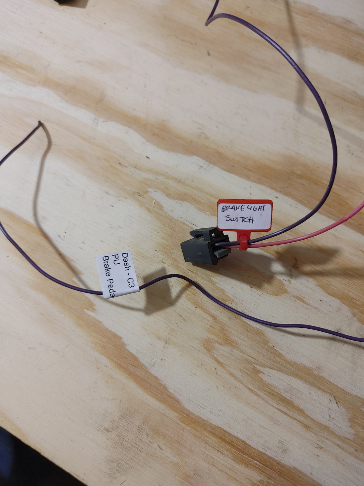
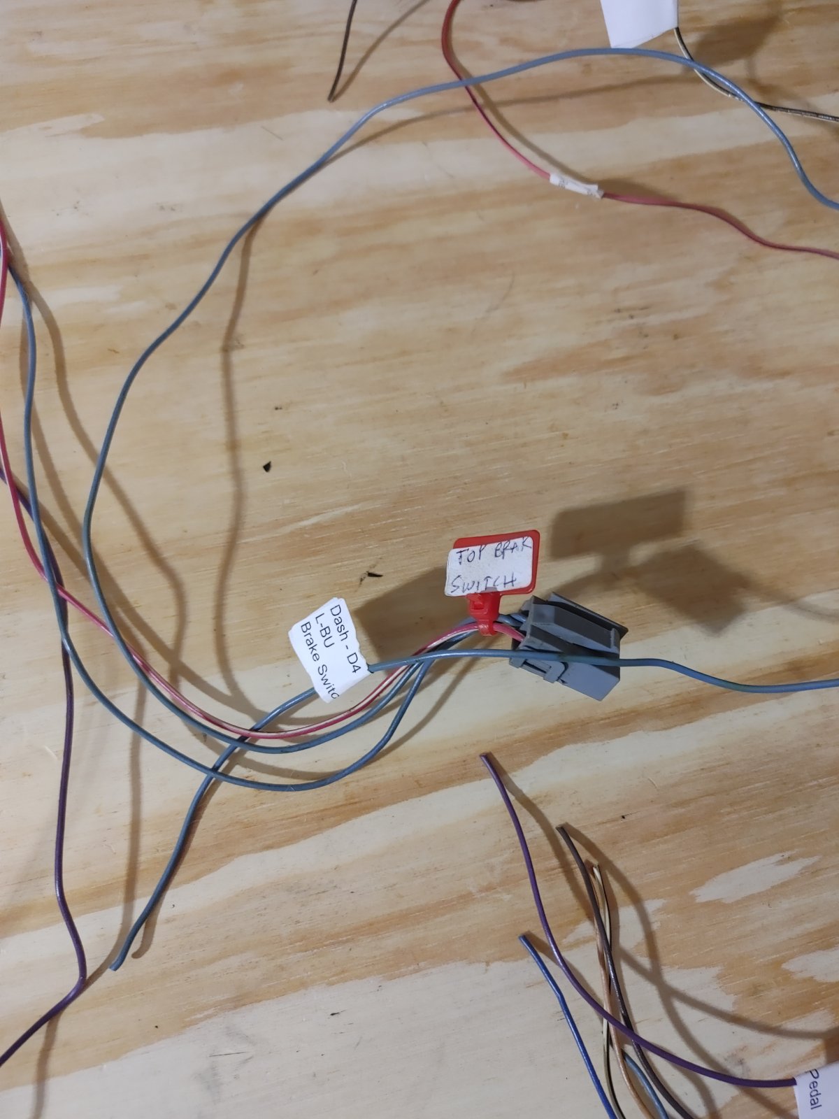
I'm not sure which one of these relates to the single connector style referenced in the video nor does cutting either of these in the middle make sense when only one wire for each is still attached with another wire already requiring extension.
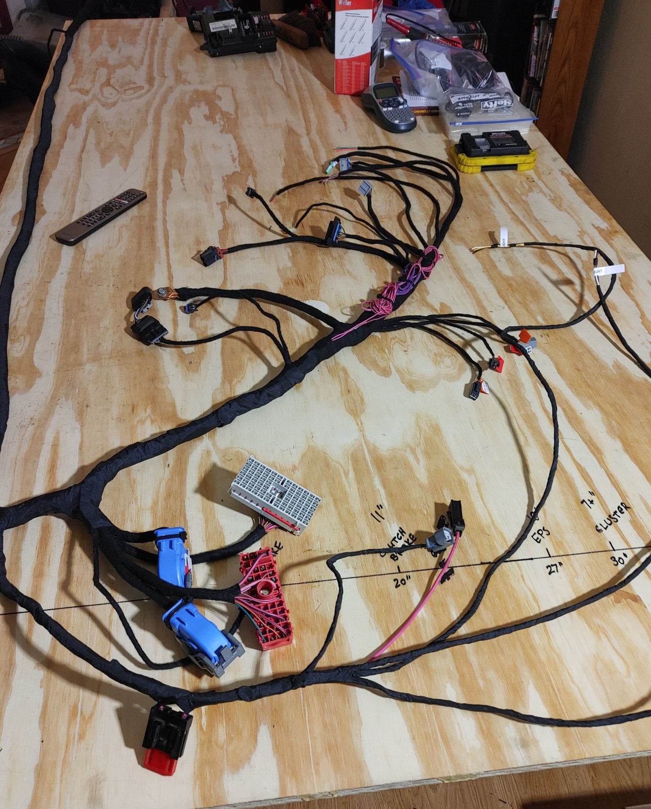
With my workspace deadline fast approaching, I skipped those for now and moved on. I got through the part for the ignition and got to Step 24 - Tape the cluster wires. I gathered the wires and noticed they were extremely short. Before I taped them I extended them out and saw they barely reach the Cluster mark on my table - there's about 4" left to extend above the line:
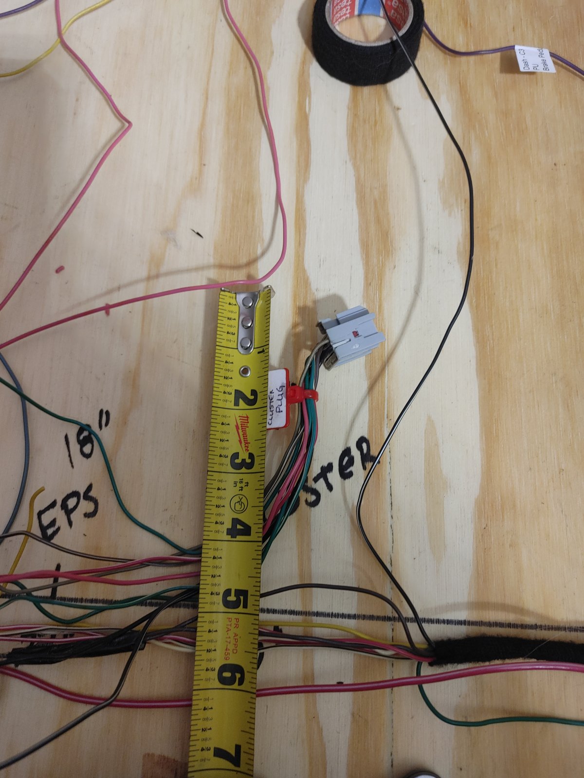
It looks like the Pink and Red/White wire are the only ones attached still and they don't have any slack nor are they bundled up anywhere - that's just as far as they go. Should I extend these or is the 4"-5" enough for the gauge cluster?
I decided to call it a night and not get too far ahead with these unfinished steps still hanging over my head.
I decided not to worry about my Boost Gauge wire and Green data wire issue above. I already have an aftermarket boost gauge and from what I learned from the forum so far is all of the green wires get connected together and the one running to the dash-to-body harness connector was running between 2 removed connectors so likely not an issue. The twisted brown wires will just hang out until I find a use for them; if not I will just tape them up if I don't figure them out before then.
Work Time: 2 hours
Completed: Wiring Harness Guide Part 8 and started Part 9 (Organizing Dash Harness)
Ignoring my labeling confusion I pressed on. The end is in sight so it stands to reason I'm starting to get off course. I had some strange connectors leftover in the dash harness that turned out to be seat heater switch connectors that I thinned out and capped off the stubs left hanging from my already-wrapped BCM trunks.
I got to the 3:47 mark of the Organizing the Dash Harness video and it shows a brake connector that is cut and tied. I know the connectors vary between years/models but I have 2 brake connectors and not just 1. Also, each of these connectors only has 1 wire each that runs to the BCM, 1 wire that was labeled previously (Brake Pedal and Brake Switch respectively), and one of them (Brake Switch connector) has a loose LT-BU wire:
I'm not sure which one of these relates to the single connector style referenced in the video nor does cutting either of these in the middle make sense when only one wire for each is still attached with another wire already requiring extension.
With my workspace deadline fast approaching, I skipped those for now and moved on. I got through the part for the ignition and got to Step 24 - Tape the cluster wires. I gathered the wires and noticed they were extremely short. Before I taped them I extended them out and saw they barely reach the Cluster mark on my table - there's about 4" left to extend above the line:
It looks like the Pink and Red/White wire are the only ones attached still and they don't have any slack nor are they bundled up anywhere - that's just as far as they go. Should I extend these or is the 4"-5" enough for the gauge cluster?
I decided to call it a night and not get too far ahead with these unfinished steps still hanging over my head.
I decided not to worry about my Boost Gauge wire and Green data wire issue above. I already have an aftermarket boost gauge and from what I learned from the forum so far is all of the green wires get connected together and the one running to the dash-to-body harness connector was running between 2 removed connectors so likely not an issue. The twisted brown wires will just hang out until I find a use for them; if not I will just tape them up if I don't figure them out before then.
Ross
Goblin Guru
The twisted brown wires are the GM High Speed LAN wires.
Here is a wiring diagram for them. You need them to run the engine.
The green wires are the GM Low Speed LAN wires.
You need access to a wiring diagram?
I found the boost signal is coming from the PCM (Powertrain control module/ engine control module)
C3 connector pin 10 is a tan wire that needs to go to your boost gauge.
Sluggonaut
Goblin Guru
These don't appear the same as the other high-speed twisted pairs I've seen elsewhere. These are from the dash-to-body connector C5/C6 and run to the BCM. I'll see if I can make sense out of the diagram.The twisted brown wires are the GM High Speed LAN wires.
Here is a wiring diagram for them. You need them to run the engine.
Per my previous post, the video had me thin one of the green wires but my label sheet included a label for the same wire the video already had me remove. I'm assuming it is not needed since the low-speed wires are simplex communication and just all need to be connected. The one removed ran between the 2 connectors that got removed so it is likely not needed like the rest that run between existing systems.The green wires are the GM Low Speed LAN wires.
My donor had an A-pillar pod with an aftermarket boost gauge. I'm not sure if it had a factory boost gauge or not, but not too worried about it as I know how to make mine work. I think the tan wire on the ECM side will just get wrapped and left where it is.You need access to a wiring diagram?
I found the boost signal is coming from the PCM (Powertrain control module/ engine control module)
C3 connector pin 10 is a tan wire that needs to go to your boost gauge.
Thanks Ross!
Sluggonaut
Goblin Guru
It must be getting late, I chased the link to the wiring diagram but don't see one.
I found the Alldata info but not sure where to look in Alldata to find the wiring diagram I need.
I found the Alldata info but not sure where to look in Alldata to find the wiring diagram I need.
Last edited:
Sluggonaut
Goblin Guru
Watching ahead, it looks like the brake connectors get reconnected again.I got to the 3:47 mark of the Organizing the Dash Harness video and it shows a brake connector that is cut and tied. I know the connectors vary between years/models but I have 2 brake connectors and not just 1. Also, each of these connectors only has 1 wire each that runs to the BCM, 1 wire that was labeled previously (Brake Pedal and Brake Switch respectively), and one of them (Brake Switch connector) has a loose LT-BU wire.
I think my approach will be to not cut anything, as the single wire between each connector and the BCM is plenty long enough to reach where they get reconnected. Both connectors have a wire to be extended back to the main harness so I will just extend those after taping the connectors where they belong in the dash harness.
I still need to figure out what the light blue wire does that is hanging off the Brake Switch connector (it was the top connector on my donor) though.
Sluggonaut
Goblin Guru
I can really use some help with figuring out which connector is which in the Alldata wiring diagrams. I've found the various BCM C1 - C4 connectors and have identified some of them, but not sure how to tell where the dash-to-body connector and its pinouts can be found.
@Lonny
I am at the first step in the Combining Harness video where I need to extend the twisted data wires. Way back at the beginning, I added the extensions to the data wires by the ECM and ran those down to the BCM.
A few posts ago, I mentioned the problem I ran into of not having either the RPD or Boost Gauge connector as expected in my 2007 SS/SC, but I did have the twisted brown wires coming out of my body-to-dash connector (pins C5 & C6).
The brown twisted pair wires were cut at the connector to get rid of the connector and they run into the already taped bundle at the BCM. I'm not sure where they go, but I can cut open all the wrapped bundles if I need to. I don't have any other twisted brown wire pairs left, so I am assuming these are what gets connected to the extensions from the ECM. I just want to make sure this is correct as it doesn't make a lot of sense to me, nor does it resemble either option in the video - running to the RPD/boost gauge down by the ignition or connecting back on the main harness.
Mine has twisted brown wires coming out of the BCM headed towards the ignition on the dash harness with the ECM extensions coming around the main-to-dash harness corner and meeting there. If there was an RPD/boost gauge at the end of the data wires I understand where they are going but if they are just running to the BCM, is it terminated in there somewhere?
Any insight from anyone would be appreciated.
Thanks in advance!
edit: I just tore everything back apart on the BCM side and the dash-to-body C5/C6 wires go to this spot on the BCM connector:
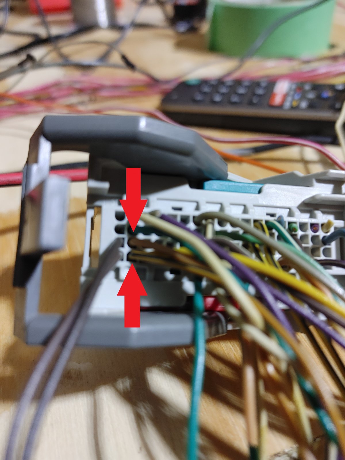
If this is BCM C2 pins 2 and 20, then these are the High Speed GMLAN Serial wires (+ and - respectively) and should be connected to my extension coming from the ECM. That's as close to a solution as I can come up with, but not sure.
@Lonny
I am at the first step in the Combining Harness video where I need to extend the twisted data wires. Way back at the beginning, I added the extensions to the data wires by the ECM and ran those down to the BCM.
A few posts ago, I mentioned the problem I ran into of not having either the RPD or Boost Gauge connector as expected in my 2007 SS/SC, but I did have the twisted brown wires coming out of my body-to-dash connector (pins C5 & C6).
The brown twisted pair wires were cut at the connector to get rid of the connector and they run into the already taped bundle at the BCM. I'm not sure where they go, but I can cut open all the wrapped bundles if I need to. I don't have any other twisted brown wire pairs left, so I am assuming these are what gets connected to the extensions from the ECM. I just want to make sure this is correct as it doesn't make a lot of sense to me, nor does it resemble either option in the video - running to the RPD/boost gauge down by the ignition or connecting back on the main harness.
Mine has twisted brown wires coming out of the BCM headed towards the ignition on the dash harness with the ECM extensions coming around the main-to-dash harness corner and meeting there. If there was an RPD/boost gauge at the end of the data wires I understand where they are going but if they are just running to the BCM, is it terminated in there somewhere?
Any insight from anyone would be appreciated.
Thanks in advance!
edit: I just tore everything back apart on the BCM side and the dash-to-body C5/C6 wires go to this spot on the BCM connector:
If this is BCM C2 pins 2 and 20, then these are the High Speed GMLAN Serial wires (+ and - respectively) and should be connected to my extension coming from the ECM. That's as close to a solution as I can come up with, but not sure.
Attachments
-
 232.8 KB Views: 115
Last edited:
Sluggonaut
Goblin Guru
Yes, the brown wires at Pins 1 & 19 go to the power steering bundle and the tan pair from the PS bundle go to the OBDII. That makes a lot more sense and easier to figure out once I identified the BCM connector as C2 and could match up the diagram.If you follow the two brown twisted wires next to your red arrows they should arrive at your power steering connector. A tan pair should leave there and go to your OBDII connector.
Thanks for confirming I'm back on the right path.
Sluggonaut
Goblin Guru
Day 17
Work Time: 3 hours
Completed: Wiring Harness Guide Part 9 and most of Part 10 (Combining the Harnesses)
Thanks to the help of Lonny and the community I was able to get through this round of obstacles and get a lot accomplished after questioning my work for a while. I'm so glad I labeled everything like I did because when the video asks for the pink wire with a knot tied at the end, I had 3 of them. lol
I was able to figure out I didn't need the Brake Reservoir wire or the Key-On power wire I decided to keep back in video 3, so the one labeled Steering Wheel Controls had to be it. Lack of labels leads to un-taping, chasing, multi-metering, and digging for diagrams. Labeling was so much easier and I appreciate the emphasis everyone places on it.
The end is definitely in sight!
I think I will hit my goal of being done by this Saturday when my workspace needs to be clear for the Christmas tree to take its place. Unfortunately, it means back outside in the cold work area to start prepping parts and my build workspace. At least I will have electricity and air for the next phase.
Sluggonaut
Goblin Guru
Day 18
Work Time: 2 hours
Completed: Wiring Harness Guide Part 10 and started Part 11 (Finishing the Harness)
Finished up Video 10 and started Video 11. Got all the grounds soldered before calling it a night - there were a lot of grounds and I only had 1 or 2 ground wires left over from the 3 ground lugs I bolted together. Looking forward to finishing up tomorrow.
Last edited:
Sluggonaut
Goblin Guru
Day 19
Work Time: 1.5 hours
Completed: Wiring Harness Guide Part 11
Finished the wiring harness tonight and just in time for my deadline of tomorrow. I still have to tear down the harness table and finish cleaning up my work area but the harness is officially done. The only real hurdles down the home stretch were some wires that got taped up along the way in the dash harness and I had some tape removal and replacement activities along the way.
Note to future builders: Make sure the TPMS receiver wires stay by the BCM so they don't end up taped down somewhere in the middle of the dash harness. Tessa tape works great on all fronts except unwrapping unless you have a nice unwrapping tool (aka knife or razor).
All the grounds tested good and the major 'gotchas' have been traced (i.e. LSJ green wire from DLC/Pin 2 back to the ECM). I will try not to have anxiety about the first start until it's time to cross that bridge.
My time tracking on the wiring harness came to a stop at 25.5 hours across 11 work sessions: