

Mayor West
Goblin Guru

- Mayor West Goblin Guru
I know I've seen the pin structure somewhere, but I can't seem to find it anywhere now. I'm trying to load up on electrical docs and store them in my google drive for myself and others to use (see signature) and this is something I'm currently in need of now as I diagnose my starting issue.
Basically, how are the wiring diagrams related to the physical pin layout themselves? Now that I've thinned out all my harnesses, it's sorta difficult to 100% confirm the layout and orientation when trying to trace wires using a wiring diagram.
Take this example of a BCM layout:
It's numbered 1 through 72, then X2. Other than visually mapping the colors to the pins (which is what I'm wanting to avoid since I've thinned everything and there's the occasional re-spliced wire that's not the original color due to my mistakes/learning)
I want to test continuity between a few lines but I want to disturb my harness as little as possible to prevent possible further issues (I did this myself so it's probably hanging out by a thread)
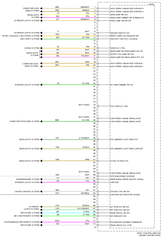
Where does everything land on the harness?
I have a similar one for the ECU but it's not really helpful for the BCM.

Basically, how are the wiring diagrams related to the physical pin layout themselves? Now that I've thinned out all my harnesses, it's sorta difficult to 100% confirm the layout and orientation when trying to trace wires using a wiring diagram.
Take this example of a BCM layout:
It's numbered 1 through 72, then X2. Other than visually mapping the colors to the pins (which is what I'm wanting to avoid since I've thinned everything and there's the occasional re-spliced wire that's not the original color due to my mistakes/learning)
I want to test continuity between a few lines but I want to disturb my harness as little as possible to prevent possible further issues (I did this myself so it's probably hanging out by a thread)
Where does everything land on the harness?
I have a similar one for the ECU but it's not really helpful for the BCM.


