Brian N's A Very Stock Extended City Goblin - 09 SS/TC Donor OKC [*SOLD*]

ctuinstra

Goblin Guru
Ran into a problem. Of all the Goblin builds, I think I am the first to have this problem which is how my luck goes. Anyways, the steering intermediate shaft interferes on the passengers side of the bulk head cut out. I can't turn it a full 360 degrees before it hits. It's hard to tell from the picture, but this is the area having issues.

It seems as if the rack shaft doesn't sit centered in the cut out, or it doesn't protrude far enough through the cut out to clear the area where the bolt goes through.

View attachment 2739
I had the same issue. It's something they should address in future builds. Also the pedal box mount hole didn't line up. Nits good to k ow that I didn't just do something wrong.
 

Briann1177

Goblin Guru
I don't want to turn this into bashing thread, but another issue I ran into was the fitment of the bottom side of the radiator spacers into the mount holes. The spacing between the mount holes was a little wide and I had to grind a bit of plastic off to get it to go in. Lonny made it look so easy by having it drop into place with a tap of his fist. :)

Other than that, it's going together fairly well. I hope to get the engine installed this weekend. You really have me worried about the engine mounts. Seems to be another common sticking area.
 

ctuinstra

Goblin Guru
Its absolutely not about bashing but sharing information. I had forgotten about that one wi the radiator mounts. I assume the new batch of radiators is off just a bit on the mounts. I ended up doing the very same thing.
 

RichRich

Well-Known Member
I had none of these issues, I first thought my peddle box didn't exactly line up but then when I got a closer look it was actually bent slightly. But I didn't have any of the issues you guys listed, including the radiator. Slid right in like it belonged
 

Briann1177

Goblin Guru
When I first dry fit the pedal box, I thought it was out of whack too. I played with it for a bit and eventually found the right spot where everything came together perfectly. I guess each build has its own set of idiosyncrasies.

Here's a few updated build pics.

I'm going against the instructions, and running my passenger side hose to the top of the radiator. I think I'd rather have a bit of air in my radiator than having flow stop in the event it becomes too low. I think this is the way the Goblin was originally designed, and Lonny said either way is fine. I put a battery mat into the bottom of the tray. It neutralizes any leakage and should protect the finish underneath.

https://www.ebay.com/i/171160132865?chn=ps

Goblin_3.jpg


I wasn't sure what to do with the key fob receiver so I used some double sided tape and a zip tie to put it on the pedal box. There are no moving clutch pedal parts up top to interfere with the connector.

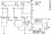
I mocked up the dash portion of the harness based on the wiring map floating around here. Like a lot of other people, I was a little leery of doing so thinking I would be limiting myself on how to run the wires. I've got to say Adam/Lonny did a great job with that. Just about everything is the right length. I am going to have to shorten the key fob receiver wires, but that's only because of where I chose to install it.

Goblin_4.jpg


I got LineX Ultra sprayed on the sheet metal. To be honest, I'd go with textured powder coat if I had to do it all over again. The spray gives the illusion of texture, but it's still pretty slick to the feet. From an aesthetic standpoint, I think it looks good.

Goblin_5.jpg


Next up is the fuel tank and engine.
 

Briann1177

Goblin Guru
Also, if anybody wants to run their radiator hoses with the original design of passenger side to the top (hot in) and driver side to the bottom (cold out), the Dayco 71796 radiator hoses look to be a perfect fit for both connections. No cutting required. The kit comes with one already, but you'll need to buy another one for about $20.
 

JSATX

Goblin Guru
My only recommendation is to leave all wires that go to the BCM longer than you need.

I’m moving my BCM off that firewall because passengers always kick it.
 

Tony

Well-Known Member
My only recommendation is to leave all wires that go to the BCM longer than you need.

I’m moving my BCM off that firewall because passengers always kick it.
Do you not have the kickplate, or are people kicking around it somehow?
 

ctuinstra

Goblin Guru
Your pedal box is different than ours. There was no way that I could have got mine to fit and bolt up.

Brian, looks like you have the extended frame also, this should help to keep passengers from hitting the BCM so easily even though you won't have to worry about it with the kick plate.
 

Briann1177

Goblin Guru
Got the fuel tank and engine installed.

How is this going to work? It looks like the turbo plumbing will run right into the cross brace.

The frame tubing isn't scratched up like the picture shows. Optical illusion.

Turbo.jpg


I have my engine mounted using these holes.

Engine_Mount_Driver.jpg


Engine_Mount_Passenger.jpg
 
Last edited:

Briann1177

Goblin Guru
We got a live one!!! I fired it up for the very first time today. I don't have any coolant in it so I didn't let it run for very long. It fired up immediately, and idles smoothly. Man, I haven't heard that engine run in 7+ months. Good to finally hear it come to life.

Oh, here's a party tip for all you turbo builders. This will make the first start--or any start really--a little more festive.

1. Cram a blue shop towel into the turbo intake.
2. Proceed to start engine.
3. Enjoy the confetti show that sprays out.
4. Pat yourself on the back for a job well done will simultaneously calling yourself a bonehead for forgetting that.

That's it for now.
 

ctuinstra

Goblin Guru
Congratulations!

I can't wait to start ours. I was hoping for this weekend, but we are waiting on the valve cover to come back from being powder coated. Also running into some backorder issues with Jegs and the fuel line (SS braided with AN fittings).

That is a great milestone. I'll bet it's a huge relief knowing that it does run! It should be down hill from here.
 

RichRich

Well-Known Member
bahaha, when I had the engine in the car still I put a towel in the output for the turbo and it shot it across the garage...couldn't imagine on the intake haha
 

Briann1177

Goblin Guru
So I spent a few hours awhile back troubleshooting why in the world the CHMSL circuit outputs 7.5V with the light not connected and the brakes not depressed, and 12.5V with the brakes depressed. Despite what the service manual says, the circuit is a tad more complicated. Once you connect the light, the voltage drops to 1V with the brakes not depressed and 12.5V with them pushed in which I think is the way it should be. If you plan on running cruise control, you'll need to keep this light on in the back of your mind.

After a little bit of research, it looks like you can use the third brake light from a '00-'04 Chevy Impala. I found a used one on eBay for $26.

CHMSL_1.jpg


I desoldered the resistors and power wires and move them to the other side of the board. That allows the the board to fit tight against the reflector housing. I'll hot glue all the seams and holes in and around the board, and I'll fill the assembly up with some epoxy. After it dries, I'll screw down a backing plate that has some mounting tabs. I'll post pics when I'm done.

CHMSL_2.jpg
 

ctuinstra

Goblin Guru
So the cruise won't work without a load on the this circuit? That's good to know because we currently don't have one and would have probably tested the the cruise and wondered why it doesn't work. Do you know how much load it needs? Do you know if the DF wing has this light?
 

Briann1177

Goblin Guru
Lonny brought this up somewhere. Im not sure you can use a simple load resistor. The brake wire tees off to your ECM, and it doesn't appear to be a simple on/off circuit. I found three different states to really make things interesting.

1. 1V with light connected and brakes not applied .
2. 7.5V open circuit voltage and brakes not applied.
4. 12V with either light disconnected or not and brakes applied.

I'm not sure what the ECM needs to see and how it uses it to determine if cruise is or isn't activated
 

Lonny

Administrator
Staff member
On my personal goblin I used a load resistor hooked to the chmsl wire and the cruise worked.
 

ctuinstra

Goblin Guru
I see what is going on here.


Brakes not applied:
The filaments of the CHMSL are used to ground source the Stop Lamp Switch circuit. So in other words, the CHMSL lamps act as a wire to ground the signal side of the Stop Lamp Switch (to 1v). Without the CHMSL in the circuit to hold the signal line low (when brakes are NOT applied), the line is able to go high (7.5 vdc you seen)by internal pull up resistors or something and this tells the ECM and EBCM that the lamps are burnt out or missing.


Brakes applied:
When the brakes are applied, then the Stop Lamp Switch connects 12 vdc from Fuse 9 to the CHMSL and the relays of the rear Stop/Turn lamps. This also tells the ECM and the EBCM that the brakes are applied.

upload_2018-3-25_15-16-35.png
 

Attachments

Top