• We've upgraded and reskinned the forum. Notice something off? Email us at [email protected] and we'll fix it.

V1 Brian's City Goblin-06/Crate MotorTC #61

Brian74
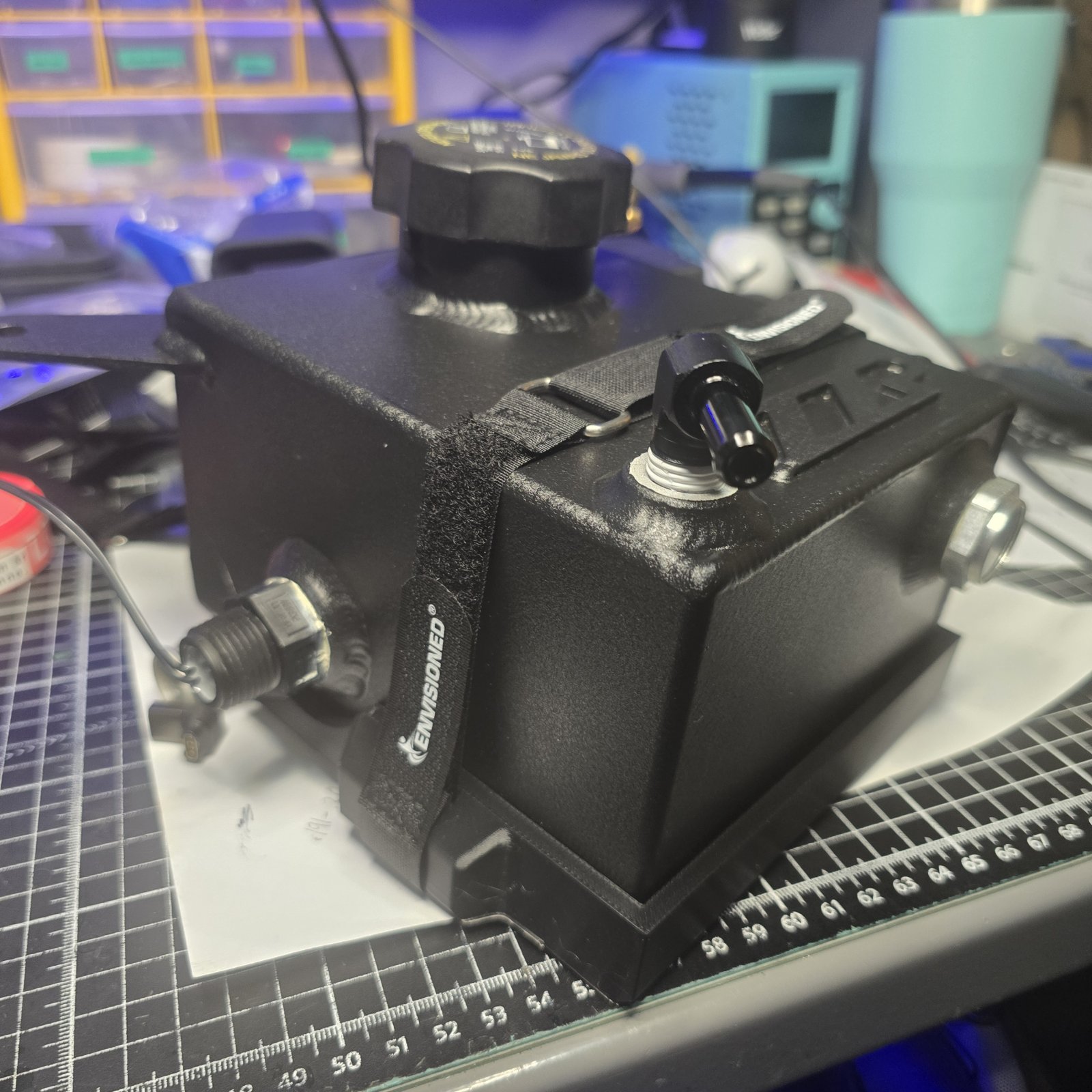
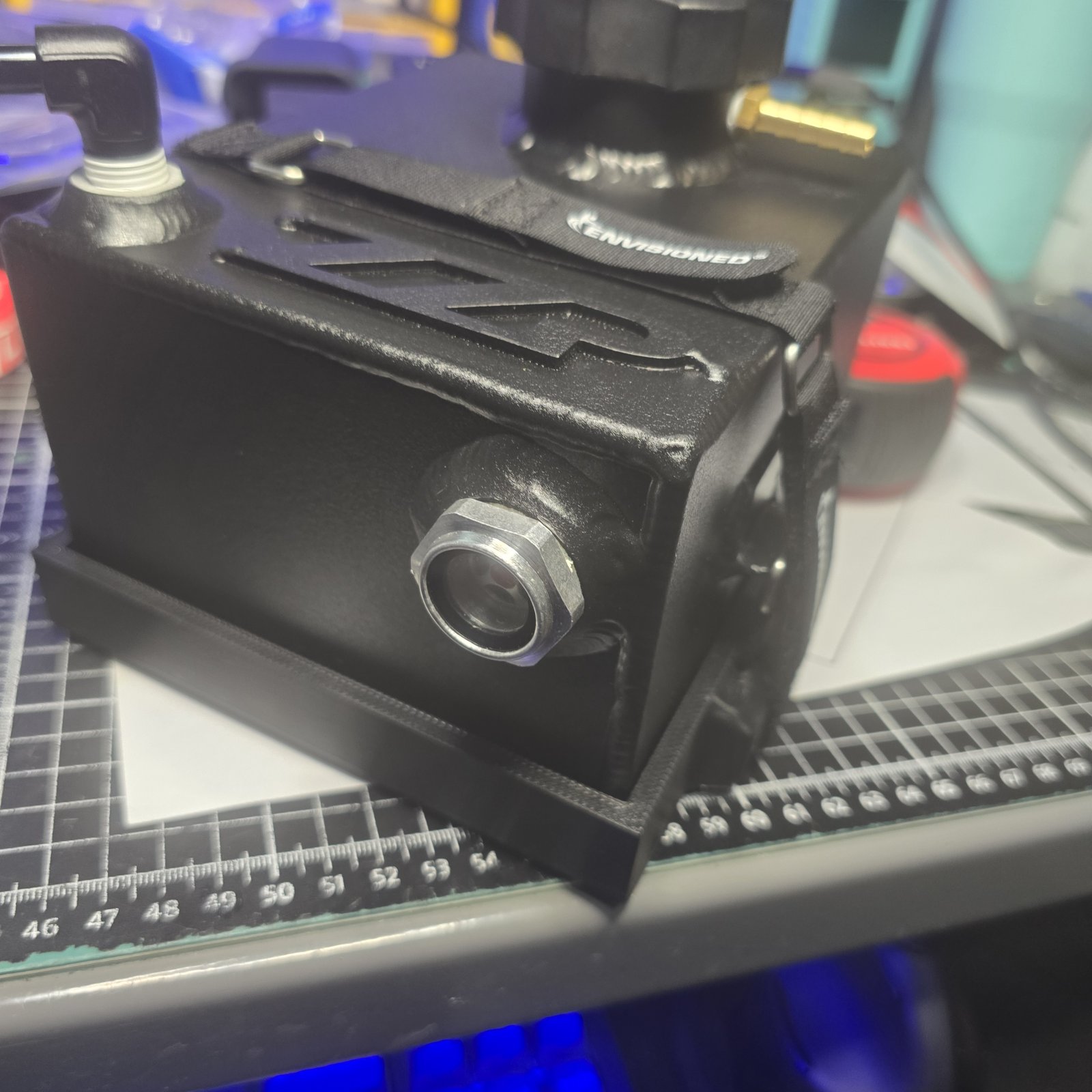
ZZP surge tank lower mount in ASA, fresh off the 3D printer. I took the lousy, useless GM style mount tab and used it to retain a 3/4" velcro strap, and it fits perfectly. I delayed 3 years of my Goblin build to design these 3D printers, but these machines are certainly proving their worth now with all the cool parts I can now make.

I finished the spoiler BOM and ordered hardware for the front spoiler, and printed out cut templates for all of the sheet metal. The next few days will be metal fabrication and welding parts for the surge tank mount and spoiler.

I will do a 2 piece splitter below the front clip and forward floor, fastened by 5/16 dzus flush mount hex fasteners.

Almost all the design stuff is finalized. The last 2 parts left are an appropriate air intake scoop and a rear diffuser.

Excited to be getting closer to sending this off to powdercoat.
20251220_205300.jpg
20251220_205305.jpg
 
Brian74
Sheet metal parts for the surge tank mount are all fully cut out. It was some long work with an angle grinder, lol. It would be nice having my new laser cutter up and running for stuff like this, but I refuse to delay this build again for any side projects. I will tack weld everything up tomorrow.

20251221_103357.jpg
20251221_120949.jpg
20251221_152546.jpg
20251222_161928.jpg
20251222_161854.jpg
 
Brian74
Surge tank mount is welded up and installed. Fits and clears the cowling.

Started in on the front wing. I did a slight redesign by adding slightly more surface area and end plates, which should improve the efficiency. Will need to re-cut the wing out. Ripped a 4x2 sheet of 1/4 6061 down to size. Will cut out the wing tomorrow.

20251223_112201.jpg
20251223_114328.jpg
20251223_124800.jpg
20251223_125120.jpg
20251223_125405.jpg
20251223_154101.jpg
20251223_161344.jpg
20251223_161357.jpg
 
Brian74
Most of my McMaster Carr order of front wing hardware showed up. Clecos, rivets, drill bits, shoulder bolts ect.

20251224_162102.jpg


I spent the day finalizing the wing shape and ensuring the angles are perfect, as well as wheel clearance. I will start cutting the wing tomorrow. The rest of the wing install should be pretty straight forward. Using 1/4" 6061 for the wing, which will make it nice and rigid.

20251224_162154.jpg


Very close to powdercoat. I still need to weld a few brackets in the engine compartment, as well as the shoulder harness mounts. I need to fabricate a proper junction for the fuel filler. I have two 3D scans left to do; one will be for a 3D printed ram air inlet for the liquid to air cooler radiator, and another ram air inlet for the airbox.
 
Rttoys
Hard to tell from your cad, but I wouldn’t put anything lower than the splitter. The way it sticks out it’ll hit on driveways and entrances to businesses. I know mine hits and it’s only a couple of inches forward of the front of the nose, plus flat and smooth with the frame. It’s pretty stout, so it just sounds bad, but doesn’t hurt anything. Just don’t want you scraping everywhere.
 
Brian74
Hard to tell from your cad, but I wouldn’t put anything lower than the splitter. The way it sticks out it’ll hit on driveways and entrances to businesses. I know mine hits and it’s only a couple of inches forward of the front of the nose, plus flat and smooth with the frame. It’s pretty stout, so it just sounds bad, but doesn’t hurt anything. Just don’t want you scraping everywhere.

Lowest point is the 1/4" aluminum support. I drew the wing end caps to be no lower than that, lined up on a side plane and projecting the tolerances. The end caps are 3D printed and also will serve as fully sacrificial "curb feelers" That was a concern of mine as well. Thanks for mentioning it.
 
Last edited:
Brian74
I got the front wing cut out today. It was much easier than I thought it would be. I used blade guides for each cut & I managed +/- .5 mm tolerances on all of the final dimensions after cutting. It was exciting test fitting it to the car finding that the fit is excellent and exactly how the CAD design showed it to be. I checked tire clearance and looks like I will be good all the way up to a 26" diameter tire at a 33 degree turn radius on the outside tire. I took some measurements, then went back into CAD and updated everything. I will add a small Gurney flap to the center... partially to deflect air upward in front of the cowling, but more to add rigidity and minimize flex and radial loading on the forward mount bushings. The aft mounts are ball joints, so no worries there.

This wing has a bit larger amount of surface area than my last design and with it being adjustable I think It will provide more than enough downforce.

Tomorrow I will start cutting out the lower mounts.

20251225_101715.jpg
20251225_111734.jpg
20251225_114808.jpg
20251225_130928.jpg
20251225_130947.jpg
20251225_131249.jpg
20251225_170138.jpg
 
Brian74
Woke up this morning and looked at the steel (aft) portion of my mount and started thinking through the welding process. I don't want to go doing a bunch of welding on the front clip without some elaborate jig and risk completely distorting it, so I simplified things a bit.

I went to a single gusset design with 2 small vertical support gussets. This assemby can be pre-welded to shape, and welding it to the front clip will require mininimal jigging and minimize heat distortion.

The rear mount piece will now be bolt-on instead, using 4 5/16 bolts, with the same vertical gusset as before. This also now makes the front wing almost 100% bolt on.

Got most of the pieces cut out today. I will start jigging everything up and welding tomorrow.

It will be nice getting the steel portion of this bs out of the way. Aluminum is much easier and more fun to work with.

20251226_183935.jpg
20251226_184011.jpg
20251226_184057.jpg
 
Brian74
Well, at least got the rear mounts welded up today. Drilled the tube ends to 1/2" and welded in the 3/8" threaded bungs. Then welded the outer and inner brackets. My welds aren't sexy but I was doing a bit of short stitching in between jig clamps to try and control heat and prevent warpage. Everything turned out perfectly square. I will weld the inner brackets to the front clip tomorrow, then I can get started on the aluminum portion (fun part).

20251227_103445.jpg
20251227_104927.jpg
20251227_105259.jpg
20251227_113348.jpg
20251227_130528.jpg
20251227_163657.jpg
20251227_161814.jpg
20251227_153054.jpg
20251227_153605.jpg
 
Brian74
Amazing that as a plan develops you are able to visualize the outcome, make changes on the fly, and get to a better solution - the mark of a true engineering mind! ;) I can't wait to see this in person!

Learning CAD has been a HUGE benefit. I couldn't see taking this on without it. Makes life so easy!
 
David
I been trying to learn Cad on fusion 360. I have created some neat stuff but it hard. Especially for a guy like me that horrible at computer stuff. Im more of a hands on guy then software, I wanted to buy a 3d scanner but way to much. So I try and design everything from scratch. Took me 3 hrs to design the thermostat housing, most of you will think im nuts.
20251227_230437.jpg
 
Brian74
I been trying to learn Cad on fusion 360. I have created some neat stuff but it hard. Especially for a guy like me that horrible at computer stuff. Im more of a hands on guy then software, I wanted to buy a 3d scanner but way to much. So I try and design everything from scratch. Took me 3 hrs to design the thermostat housing, most of you will think im nuts. View attachment 55050

Not bad for 3 hours. Raw design in CAD is obviously best suited for 3D printed parts, unless you have the capabilities to make CNC or sheet metal parts. Mockups all day long for fit, but functional parts are a gamble. Certain things are perhaps better off not 3D printed, or require a certain extent of knowledge of what polymers will handle the design, as well as how they can be 3D printed in a way that will maximize the design in terms of strength and efficiency.

As far as scanners are concerned, they are great, but not what people assume. Any good scanner will provide you with a massive, accurate point cloud of dots. Most software will convert that to a mesh natively, but in order to get it into a true CAD/solid file, it will require expensive software and/or extensive reworking. Scanners IMO are more efficient for 3D measurements; unless you are purely scanning to replicate and can get a good enough scan that can then be 3D printed.... Otherwise you need to be skilled in mesh design as well as solid design.
 
David
Not bad for 3 hours. Raw design in CAD is obviously best suited for 3D printed parts, unless you have the capabilities to make CNC or sheet metal parts. Mockups all day long for fit, but functional parts are a gamble. Certain things are perhaps better off not 3D printed, or require a certain extent of knowledge of what polymers will handle the design, as well as how they can be 3D printed in a way that will maximize the design in terms of strength and efficiency.

As far as scanners are concerned, they are great, but not what people assume. Any good scanner will provide you with a massive, accurate point cloud of dots. Most software will convert that to a mesh natively, but in order to get it into a true CAD/solid file, it will require expensive software and/or extensive reworking. Scanners IMO are more efficient for 3D measurements; unless you are purely scanning to replicate and can get a good enough scan that can then be 3D printed.... Otherwise you need to be skilled in mesh design as well as solid design.

Yea my plan is to print the housing out and make sure everything lines up. Then send the STL file to get made.
 
Last edited:
Brian74
****... Welding takes forever. Its not so much the welding itself, but the **** jigging and clamping required.

Today I added strengthening gussets to the mount brackets. I realized that yesterday I was not running enough heat, so I covered over all of my previous welds while I was at it. Much cleaner welds now. I probably overkilled it, but the rear wing brackets are done. I started looking at the aluminum stuff and the front mount. My concern now is the strength of the 1/4" thick lower L bracket. I used some aluminum that I had lying around my shop for the mockup, to find out later on it was bent (tweaked) and I question the strength. Not sure if it is T6 6061, or if that will suffice. I could just go with a thinner wall cold roll steel L bracket instead of the aluminum altogether and likely be better off. Would hate to have to drop this part of the project for a few days to wait for the metal to ship, but there is also other stuff to do.

1000067386.jpg
1000067387.jpg
1000067390.jpg
1000067391.jpg
1000067392.jpg
1000067393.jpg
1000067394.jpg
 
Brian74
Not a super productive day, but I needed a break from the garage. I refined some last minute designs of the front wing mount and designed & started 3D printing all of the templates needed for machining and drilling the aluminum front wing brackets.

I started a print of one of the wing end caps.

Moving forward, I will 3D scan my cold air intake and the intake portion of my intercooler radiator and CAD design and 3D print some nice contoured ram air scoops for both.

I'm nearing the end of all the mods I planned to add to my Goblin. The only other idea I have is adding an electronic full exhaust bypass solenoid, controlled by an open/close button on the steering wheel. I still need to fit the exhaust and determine proper placement.

20251229_151501.jpg
20251229_151440.jpg
20251229_151359.jpg
20251229_151355.jpg
20251229_151413.jpg
 

Attachments

  • 20251229_151413.jpg
    20251229_151413.jpg
    270.8 KB · Views: 68
Back
Top