
-
We've upgraded and reskinned the forum. Notice something off? Email us at [email protected] and we'll fix it.
You are using an out of date browser. It may not display this or other websites correctly.
You should upgrade or use an alternative browser.
You should upgrade or use an alternative browser.
V1 Brian's City Goblin-06/Crate MotorTC #61

Desert Sasqwatch
Bigfoot Goblin

- Desert Sasqwatch Bigfoot Goblin
Floor blink!!!  Look great.
Look great.


Classy
Well-Known Member

- Classy Well-Known Member
I just read through your whole build, very nice, I am curious how the dash effects getting in and out of your goblin though. Also, how well can you see your screen with the steering wheel sitting in the seat?
You also made me feel better about planning to take over a year to build my future goblin
You also made me feel better about planning to take over a year to build my future goblin

Brian74
Goblin Guru

- Brian74 Goblin Guru
I just read through your whole build, very nice, I am curious how the dash effects getting in and out of your goblin though. Also, how well can you see your screen with the steering wheel sitting in the seat?
You also made me feel better about planning to take over a year to build my future goblin
The dash makes no difference getting in or out. When I first mocked it up, I sat in the car and set all the view and reach points to be fully visible/accessible while buckled in.
Brian74
Goblin Guru
- Brian74 Goblin Guru
So, at this point, what is your BCM still doing for you?
I am planning on running gauges or a screen in the same spot for better visibility while driving
Usung the BCM for all lights/horn/ cruise control enable. It also supplies driver voltage for coolant & brake fluid level as it was originally designed. It provides the ECM with brake pedal position. I believe it is required for the theft deterrent module to be able to interface with the ECM.
Also using the BCM door close trigger circuit to control my courtesy lights through the RFID ignition curcuit.
Brian74
Goblin Guru
- Brian74 Goblin Guru
Since the Goblin uses no AC, door locks, wiper, power windows, rear defog ect, there are a wealth of leftover unused, protected transistorized driver circuits and relays in the fuse box/BCM that can be assigned to run other items. I ended up using the original high-amperage rear defog relay circuit to run my liquid intercooler fan, and the wiper relay to run my center high mounted stop lamp (as my fuse box is from an LSJ and lacks the same relay that the LNF has). All power/lighting to my dash components are on the original fused driver circuits from the BCM.
It simply comes down to how creative you want to get with it. No sense in adding extra relays or circuits when its already readily available in the stock components.
It simply comes down to how creative you want to get with it. No sense in adding extra relays or circuits when its already readily available in the stock components.
Brian74
Goblin Guru
- Brian74 Goblin Guru
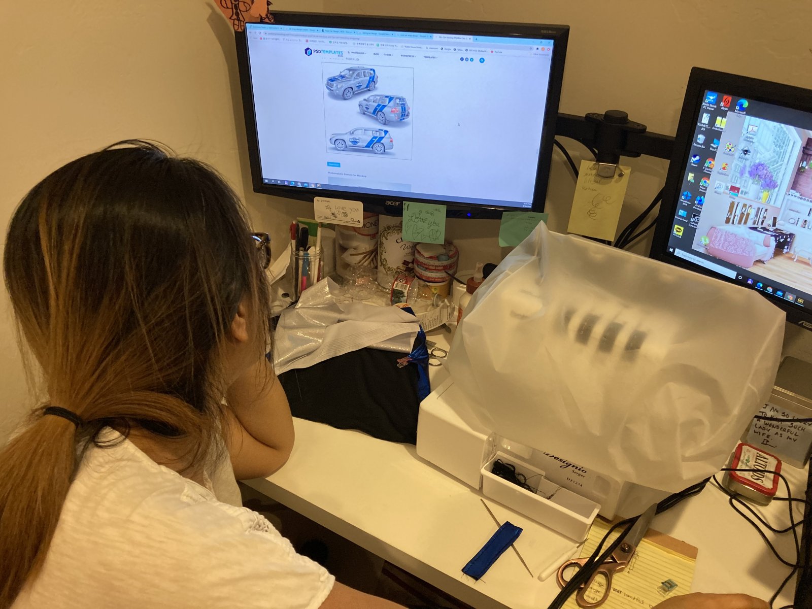
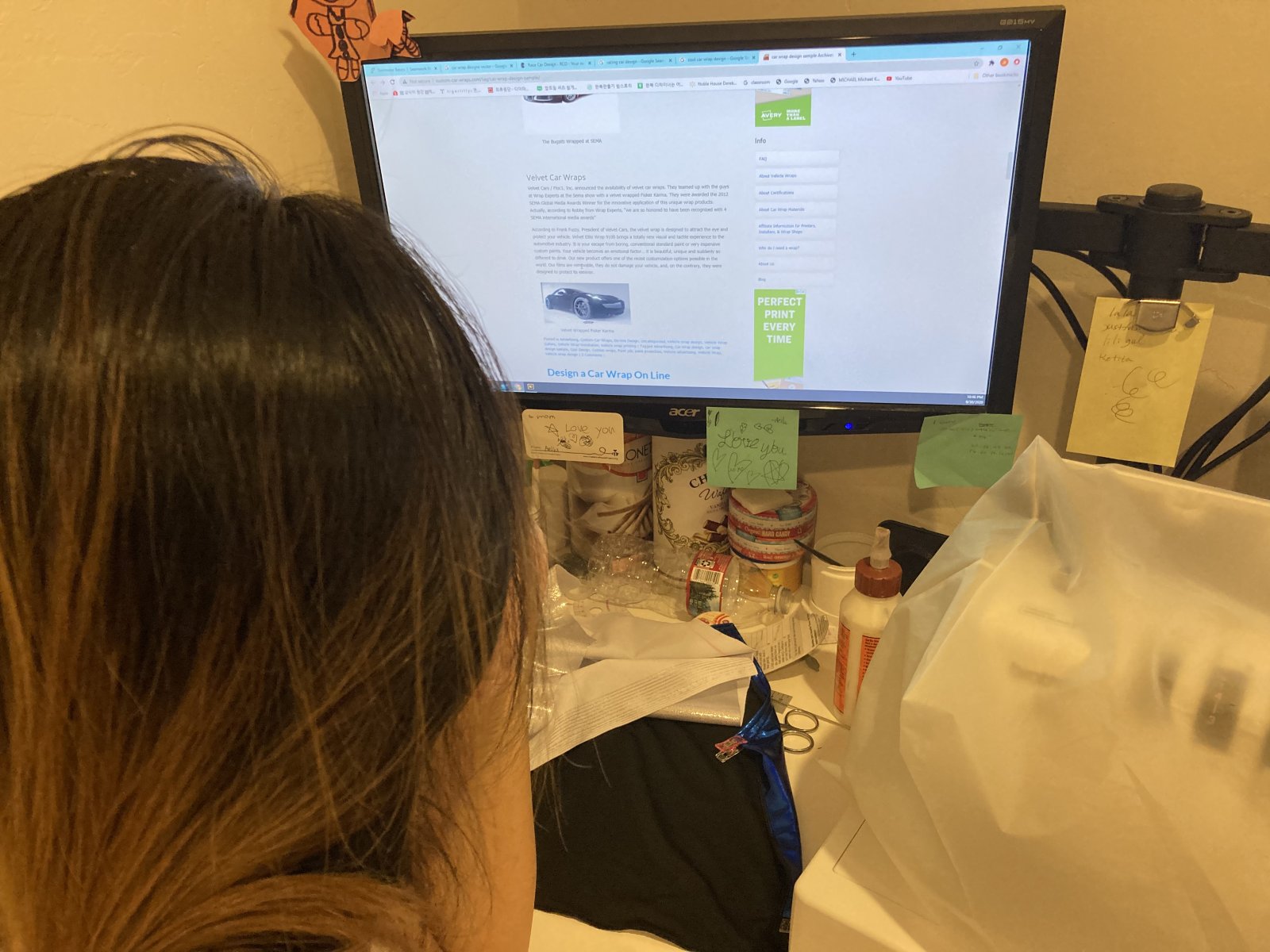
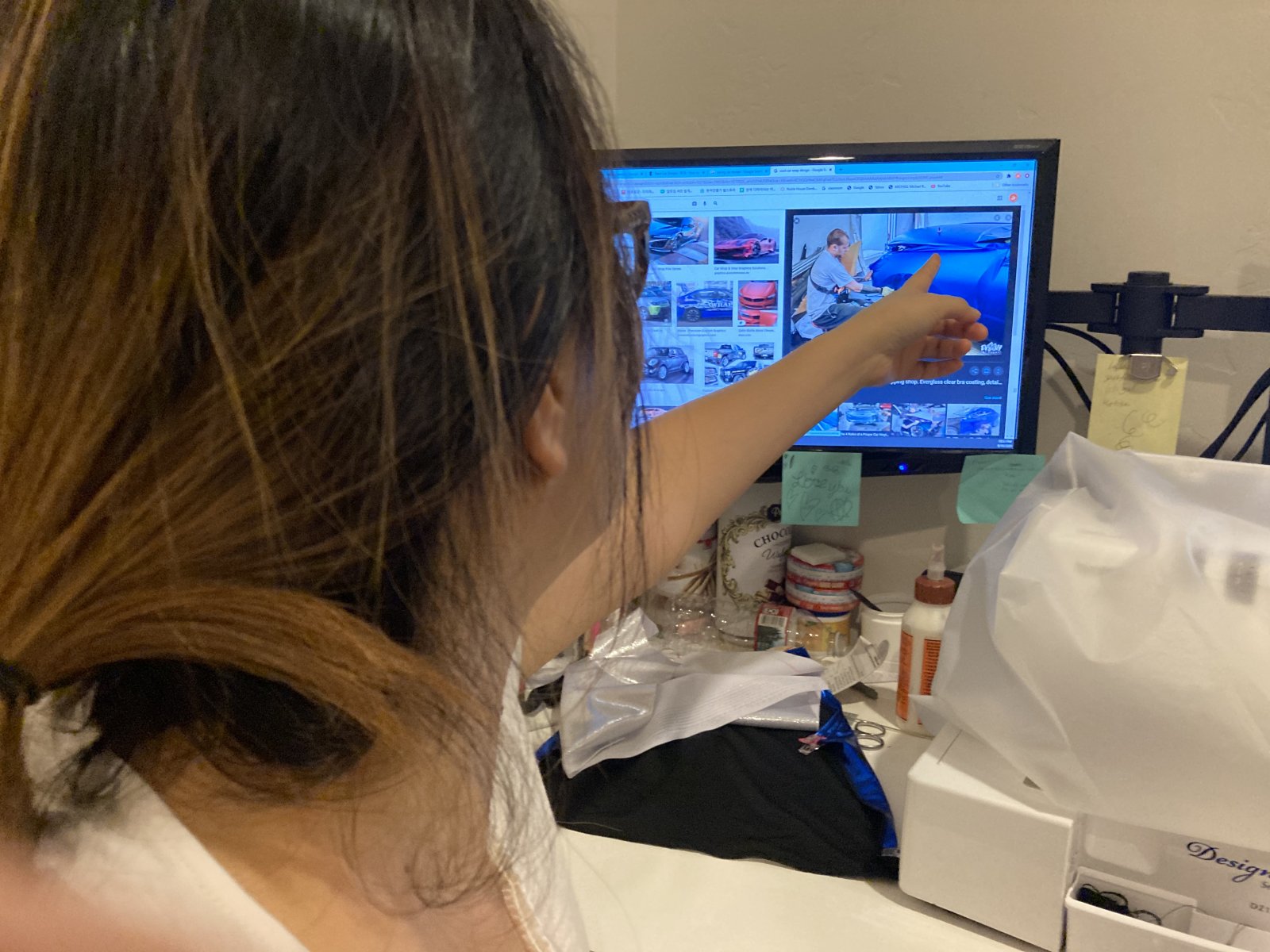
My wife; an Adobe Illustrator nerd, who I've yet to dare ever challenge to a design contest, has gained an interest in the .eps files and the cowling/side vinyl wrap process. She totally gets the concept, procedure, and the look we're after, as well as a need to explain that entire process to me.
I think she will come up with something pretty **** amazing.
I think she will come up with something pretty **** amazing.
Desert Sasqwatch
Bigfoot Goblin
- Desert Sasqwatch Bigfoot Goblin
Posting at 1:00 am? 
Brian74
Goblin Guru
- Brian74 Goblin Guru
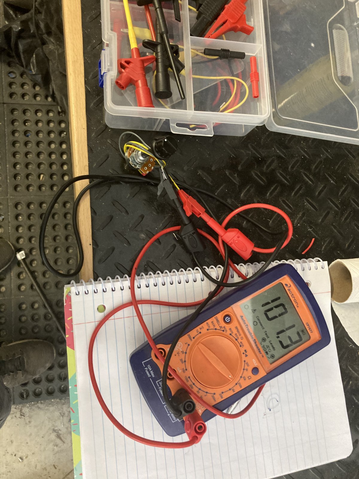
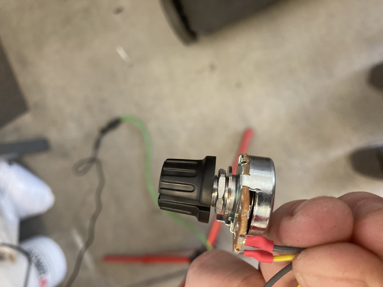
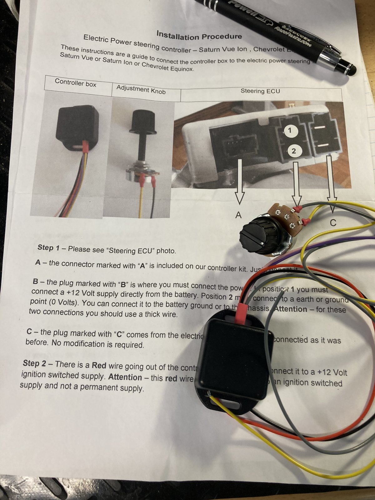
Patching up some loose ends with the dash wiring... I hate afterthoughts, but I am adding in this custom adjustable power steering controller because it will be totally worth it.
I am also making a dash mount for the factory ambient light sensor, which will provide headlamp operation in the automatic mode.
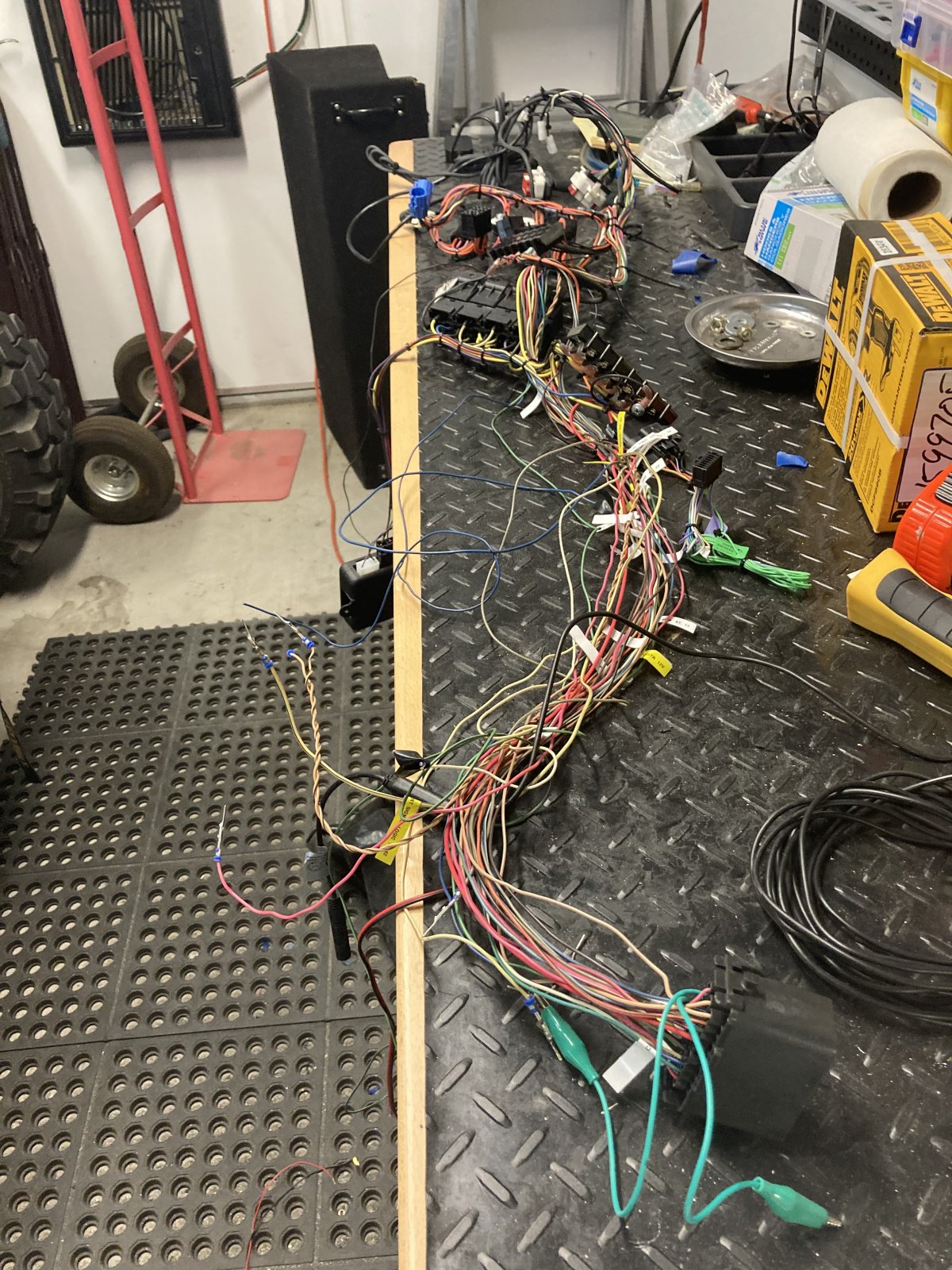
I will have a total of 32 wires leaving the dash harness for which I will build 2 18 pin GT150 connectors.
I found one last bit of real estate on the dash to mount the EPS rheostat. Since I am now removing the original factory EPS unit from the CAN bus, I will need to add a 120 ohm parallel termination resistor between the high/low data lines in order to create a 60 ohm reading between the ECM to maintain data integrity. Another **** drive across town for a 99 cent part...
I was still having CAN diagnostic communications problems with the Strada panel plugged in. The manufacturer's solution was to unplug the Strada any time I need to pull ECM or BCM live data. I call bullshit on that one.
My solution instead was to add in diodes upstream on the CAN bus. That worked, except the Aeroforce gauge didn't like it (probably because it uses its own internal CAN bus termination and doesn't like the Strada being on the same bus. I will now add the diodes further upstream, just before the Strada display and after the Aeroforce. It should make the Strada invisible on the CAN bus, so in theory, that should work. Lets pray it does...
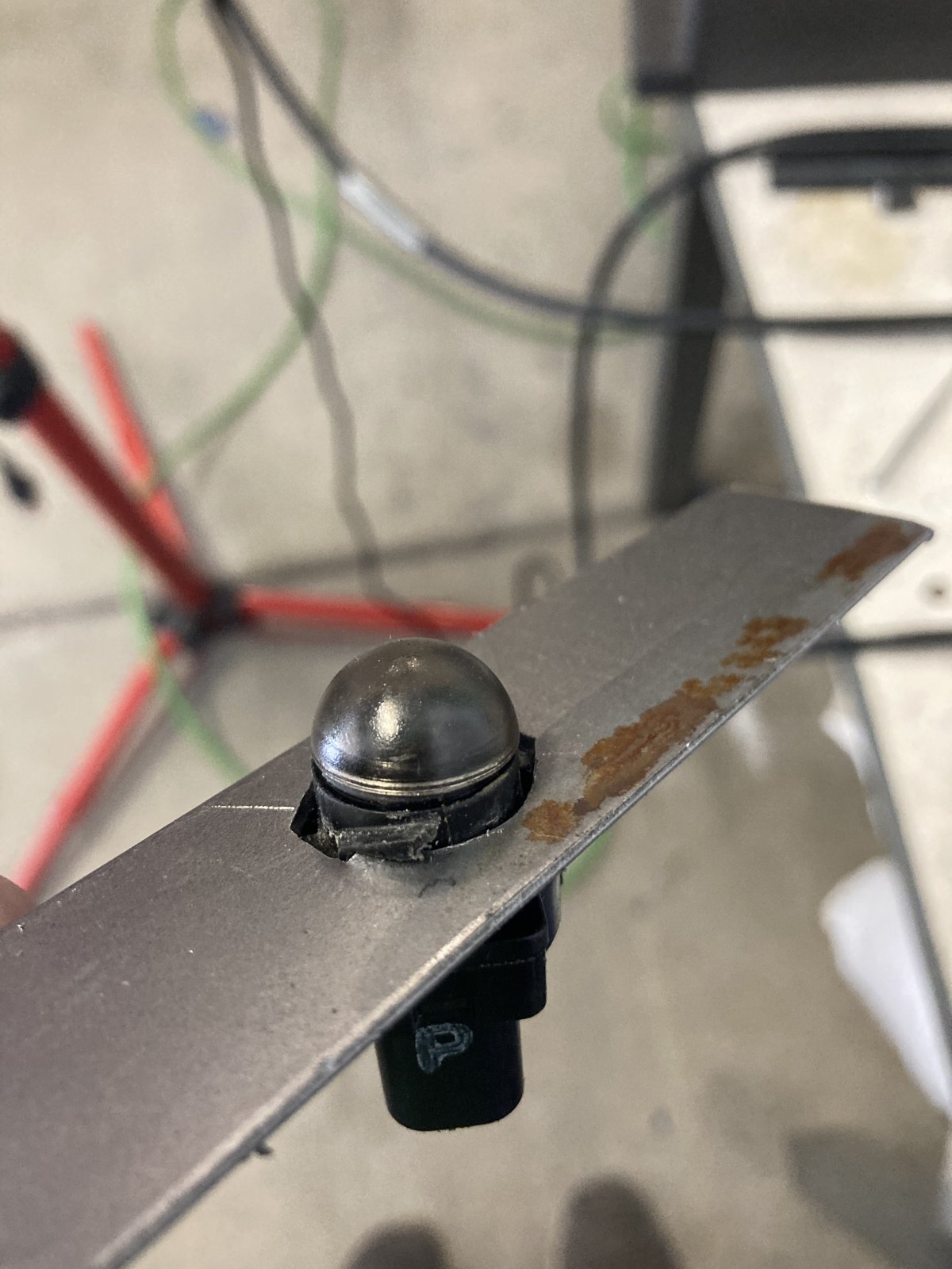
I am also making a dash mount for the factory ambient light sensor, which will provide headlamp operation in the automatic mode.
I will have a total of 32 wires leaving the dash harness for which I will build 2 18 pin GT150 connectors.
I found one last bit of real estate on the dash to mount the EPS rheostat. Since I am now removing the original factory EPS unit from the CAN bus, I will need to add a 120 ohm parallel termination resistor between the high/low data lines in order to create a 60 ohm reading between the ECM to maintain data integrity. Another **** drive across town for a 99 cent part...
I was still having CAN diagnostic communications problems with the Strada panel plugged in. The manufacturer's solution was to unplug the Strada any time I need to pull ECM or BCM live data. I call bullshit on that one.
My solution instead was to add in diodes upstream on the CAN bus. That worked, except the Aeroforce gauge didn't like it (probably because it uses its own internal CAN bus termination and doesn't like the Strada being on the same bus. I will now add the diodes further upstream, just before the Strada display and after the Aeroforce. It should make the Strada invisible on the CAN bus, so in theory, that should work. Lets pray it does...


