
-
We've upgraded and reskinned the forum. Notice something off? Email us at [email protected] and we'll fix it.
You are using an out of date browser. It may not display this or other websites correctly.
You should upgrade or use an alternative browser.
You should upgrade or use an alternative browser.
V1 Brad's City Goblin - 10 SS/TC Donor, NY Build - FOR SALE

ctuinstra
Goblin Guru

- ctuinstra Goblin Guru
Yeah, I'm thinking that's a much better way to go. They are so much more efficient and don't have to dissipate all that power. Here is a link to more available. Too many choices!
TI buck converters
ctuinstra
Goblin Guru
- ctuinstra Goblin Guru
That is all correct but the biggest issue it getting the input voltage (13.8v) down to 3.3v while passing .270A. So there is 2.8W of power that has to be used or dissipated as heat. That's terribly inefficient.What's the forward voltage on those LEDs? 2.9V.
R = E/I
(3.3 - 2.9)/.27
1.5 ohms
P=IE
P=.27 * (3.3 - 2.9)
P = .108W
If my math is correct and thinking along the same lines as Brad.
This is calculating the power dissipation for the current limiting resistor, not the entire circuit. Even at a 1/4w, I'll bet it still gets a bit warm dissipating .108w.P=IE
P=.27 * (3.3 - 2.9)
P = .108W
Briann1177
Goblin Guru
- Briann1177 Goblin Guru
How do you figure 2.8W? The dissipated power basically will remain the same on both the input/output side. You do have to factor in a bit of loss due to the efficiency of regulator but even at 50% efficiency, that's still barely a 1/4W of input power.
Think of it this way. If you run your 240V compressor off 120V, the consumed power will remain the same, but the current will double.
Think of it this way. If you run your 240V compressor off 120V, the consumed power will remain the same, but the current will double.
- bradr Well-Known Member
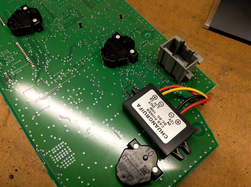
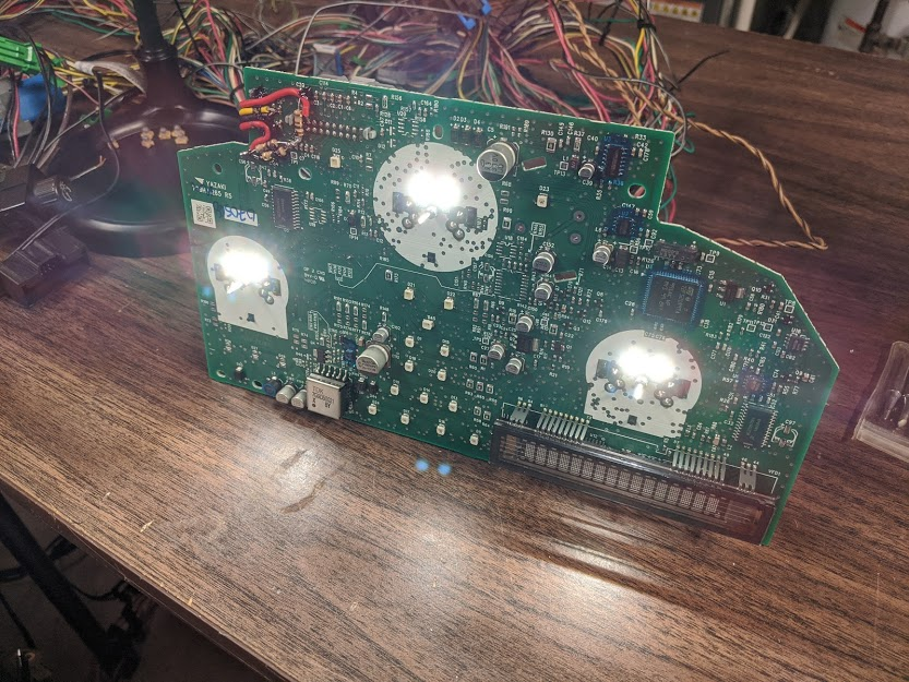
Net result of my testing - the linear regulator worked but got warmer than I liked for being placed inside the cluster as ctuinstra previously found. I ended up using a cheap chinese buck converter that drops the battery voltage to 3.3 volts and then 1.5 ohms worth of resistors. The buck converter is rated at 3 amps (way overkill) and does not generate any heat.
I only had to cut one trace and trim some of the plastic on the back cover of the cluster to fit the buck converter. The lighting looks amazing and was totally worth the effort.
The light leaking out behind the needles is because they are not pushed on all the way.
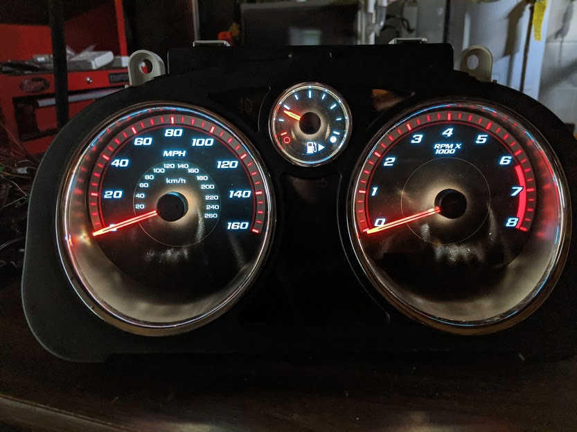
I only had to cut one trace and trim some of the plastic on the back cover of the cluster to fit the buck converter. The lighting looks amazing and was totally worth the effort.
The light leaking out behind the needles is because they are not pushed on all the way.
ctuinstra
Goblin Guru
- ctuinstra Goblin Guru
Net result of my testing - the linear regulator worked but got warmer than I liked for being placed inside the cluster as ctuinstra previously found. I ended up using a cheap chinese buck converter that drops the battery voltage to 3.3 volts and then 1.5 ohms worth of resistors. The buck converter is rated at 3 amps (way overkill) and does not generate any heat.
I only had to cut one trace and trim some of the plastic on the back cover of the cluster to fit the buck converter. The lighting looks amazing and was totally worth the effort.
Love it! I wish I would have thought of the buck converter when doing mine. Eh, either way works, yours is easier to do.
Sure does put the old filament bulbs to shame!
It's hard to get a good picture of how they really look. So much better in person.
- bradr Well-Known Member
You are not wrong, they look way better in person. I can't believe the improvement. Thanks for doing the legwork on this one!Love it! I wish I would have thought of the buck converter when doing mine. Eh, either way works, yours is easier to do.
Sure does put the old filament bulbs to shame!
It's hard to get a good picture of how they really look. So much better in person.
Briann1177
Goblin Guru
- Briann1177 Goblin Guru
Did you use the pad that corresponds to pin 8 on the cluster connector for you voltage converter input?
Also curious to know what trace(s) get modified. Do you have a schematic for the cluster board?
Also curious to know what trace(s) get modified. Do you have a schematic for the cluster board?
- bradr Well-Known Member
Did you use the pad that corresponds to pin 8 on the cluster connector for you voltage converter input?
Also curious to know what trace(s) get modified. Do you have a schematic for the cluster board?
**I did not take pictures of what I did, so I stole a picture from ctuinstra to mark up what I did. This picture is only for reference - please ignore the wires and resistor. Because there was a wire in the way of one of the traces, I represented the trace by the yellow lines.**
Parts used:
Procedure:
- Desolder old bulbs carefully as to not damage the pads on the board.
- Solder in the LEDs - see my previous post HERE about orientation and shifting the LED as to not short the cathode.
- Cut the trace as shown in picture below
- Trim out the plastic reinforcements on the back cover of the cluster to clear the height of the buck converter.
- Glue the buck converter to the back of the circuit board.
- Solder in buck converter to the points shown in the picture below. Both grounds go to the same point.
- Enjoy!
- You can use a 1/4w resistor, I wanted to play it safe.
- You can use a combination of resistors to tune the current or if you do not have exactly 1.5 ohms.
- 1.5 ohms was used to target 45mA per LED of the 60mA max they can handle.
- There are MANY buck converters that will work, many smaller. This one is way overkill, but it was cheap and already in an enclosure.
- You will no longer be able to dim the cluster - I would recommend removing and shorting the dimmer wires in the car.
- I am guessing this buck converter is not isolated, but assuming it is, attaching the two grounds together like I did would remove any isolation that the buck converter might have provided. There is no safety or electrical reason in this application to require isolation.
Actual picture of my cluster after modification - the three 1 ohm resistors equal 1.5 ohms in this configuration.
Back plastic trimming.
Last edited:

Ross
Goblin Professor

- Ross Goblin Professor
I need this guide to follow.**I did not take pictures of what I did, so I stole a picture from ctuinstra to mark up what I did. This picture is only for reference - please ignore the wires and resistor. Because there was a wire in the way of one of the traces, I represented the trace by the yellow lines.**
So thankful to Chad and Brad for forging the way on this!

Desert Sasqwatch
Bigfoot Goblin

- Desert Sasqwatch Bigfoot Goblin
Organized and clean, pretty good for a sparky! 
- bradr Well-Known Member
Good news: I figured out how to reset the odometer in the BCM.
Bad news: The current method I am using requires the BCM to be opened up to directly access the EEPROM and is not DIY.
So far I can reset the mileage to 0, but can't enter a specific value. There is some black magic going on inside the BCM related to mileage and may be encrypted, formula driven, or I might just be too dumb to figure it out at first glance. All that said, it is not worth my time to reverse engineer it. Other things I can edit are the VIN stored in the BCM and the BCM serial number.
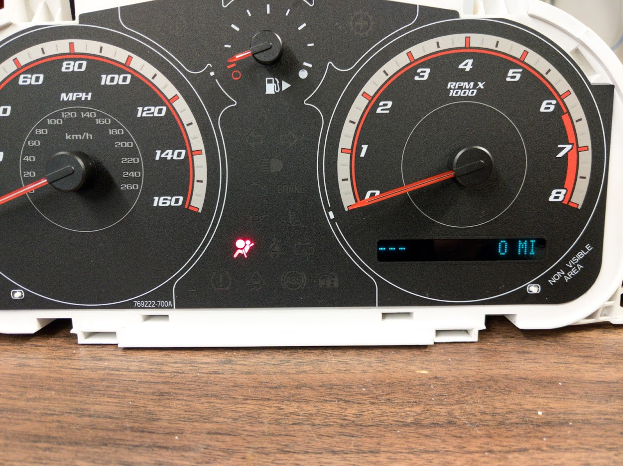
My testing platform:
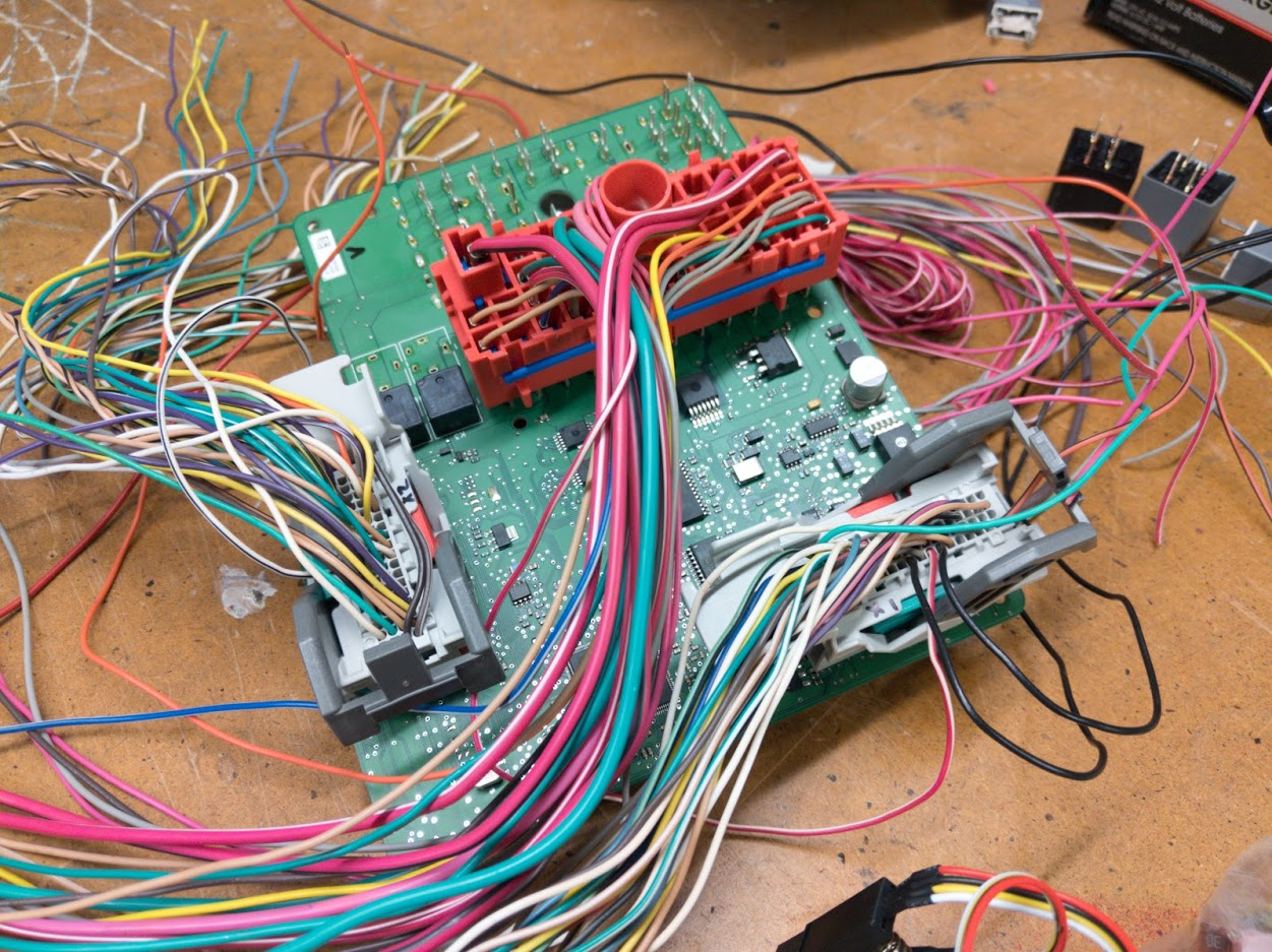
Bad news: The current method I am using requires the BCM to be opened up to directly access the EEPROM and is not DIY.
So far I can reset the mileage to 0, but can't enter a specific value. There is some black magic going on inside the BCM related to mileage and may be encrypted, formula driven, or I might just be too dumb to figure it out at first glance. All that said, it is not worth my time to reverse engineer it. Other things I can edit are the VIN stored in the BCM and the BCM serial number.
My testing platform:
Desert Sasqwatch
Bigfoot Goblin
- Desert Sasqwatch Bigfoot Goblin
One of these, a troubleshooter's best tool.
Programmer Test Clip Soic16 Sop16 Dip16 Pin Adapter Board IC Lead Pitch 1.27mm for sale online | eBay
Find many great new & used options and get the best deals for Programmer Test Clip Soic16 Sop16 Dip16 Pin Adapter Board IC Lead Pitch 1.27mm at the best online prices at eBay! Free shipping for many products!
www.ebay.com
ctuinstra
Goblin Guru

TheNuker
Goblin Guru

- TheNuker Goblin Guru
Yeah exactly, I would like to start at zero with the new engine/trans.I'd like to least turn it back to when we finished the car. Missouri just passed a new law and now the Motor Vehicle Safety Inspections are only required on vehicles over 149,999 miles. I don't want to have to take it in to get it inspected any sooner than I have to.
Nuker-
Desert Sasqwatch
Bigfoot Goblin
- Desert Sasqwatch Bigfoot Goblin
This is the company that some have used with good results. This has been posted before, thought it might be needed again here.


Similar threads

- Replies
- 2
- Views
- 660
- Replies
- 168
- Views
- 19K

- Replies
- 0
- Views
- 1K


- Replies
- 25
- Views
- 5K