• We've upgraded and reskinned the forum. Notice something off? Email us at [email protected] and we'll fix it.

V1 Brian's City Goblin-06/Crate MotorTC #61

Brian74
Nice, what did you do to the harness to make it work. Im interested in doing some like that.

My dash harness is built from scratch. CAN bus supplies most of the signal data to the AIM; you can see what is available for the Cobalt on their website. Added in additional analog inputs for oil PSI and a few additional signals (cannot remember which ones). I might have more details on it posted earlier in my build log.
 
Brian74
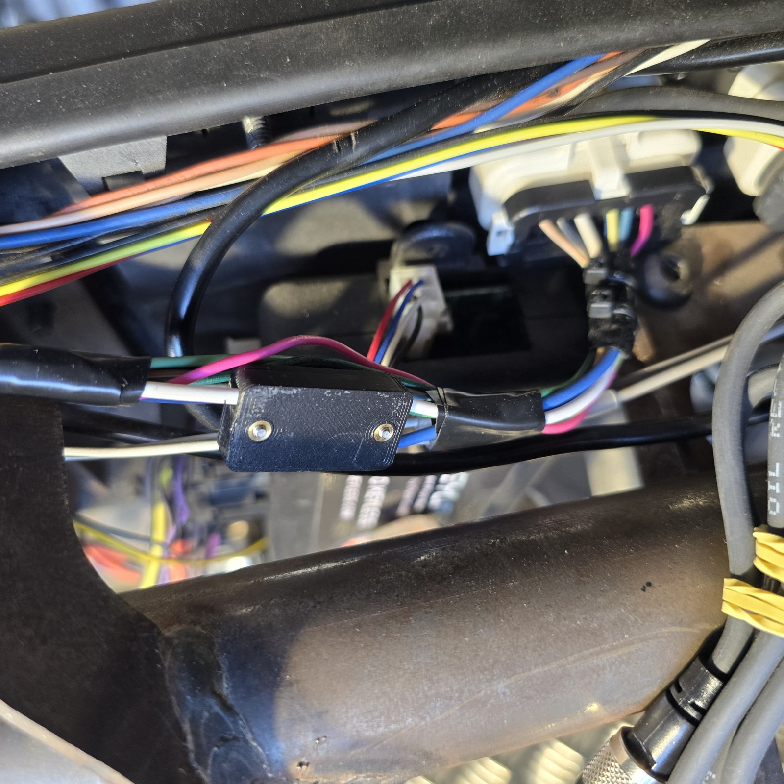
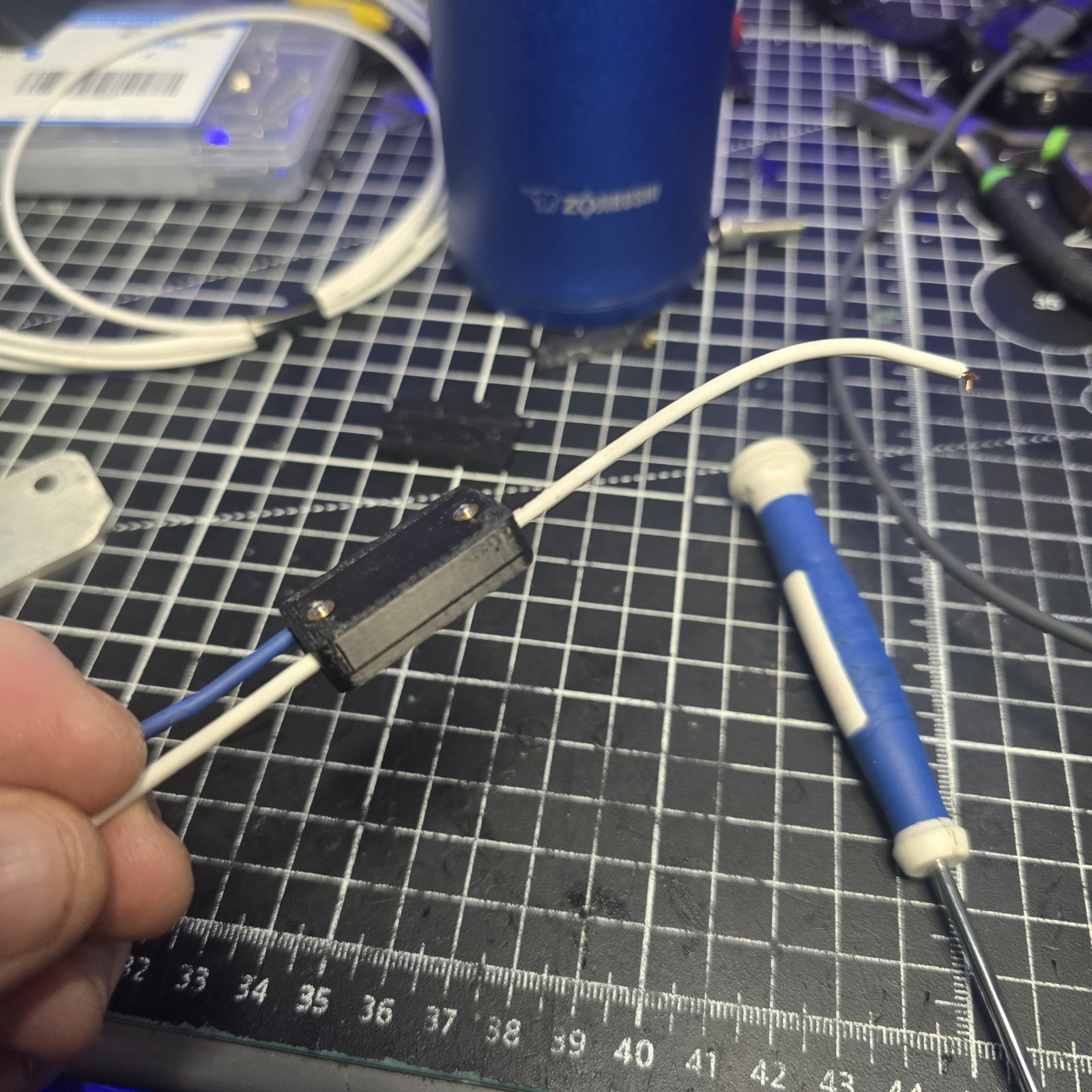
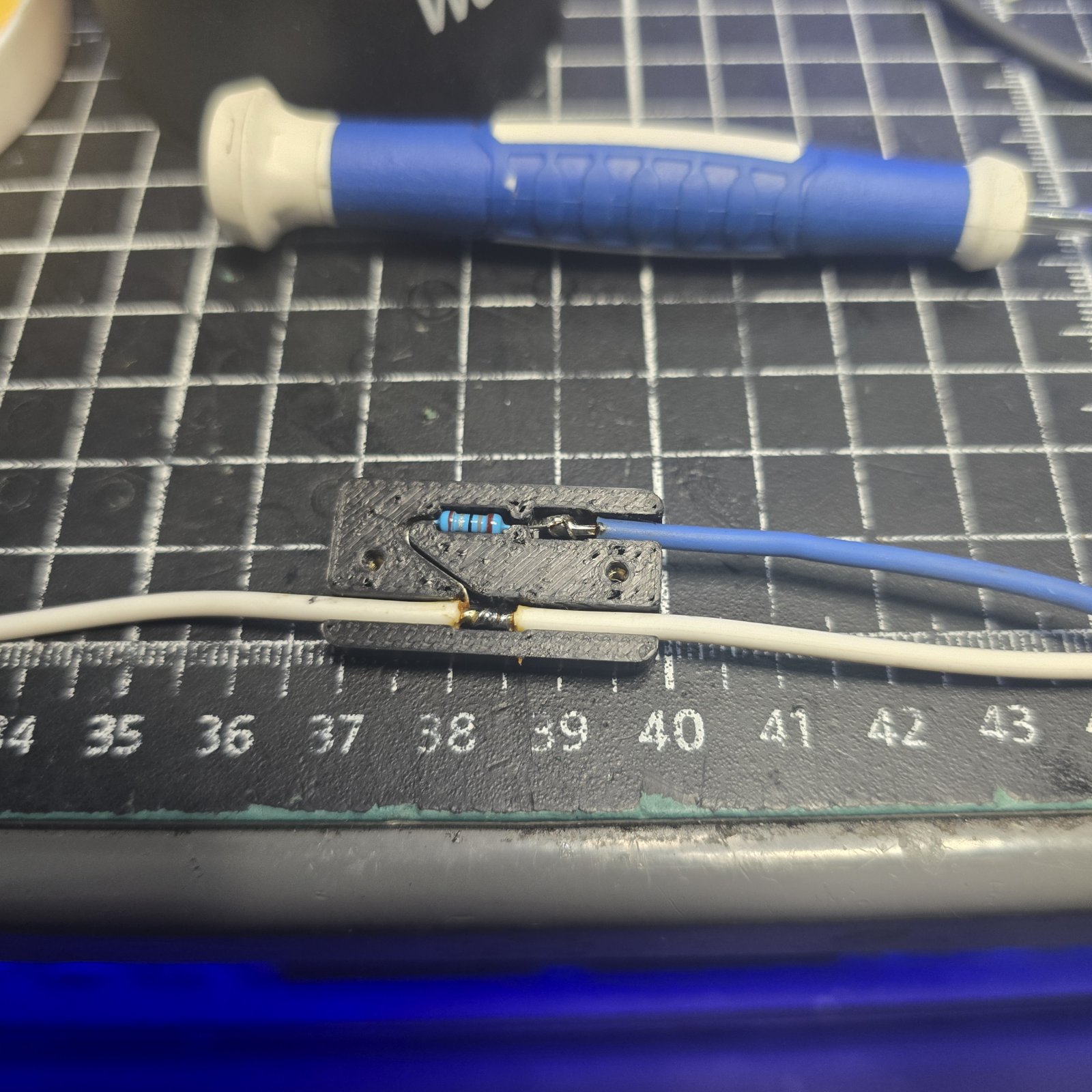
Still working away at this at every opportunity. Last week I went through my dash harness to make sure I had all of the remaining dash inputs set up right. I never did get the oil pressure sending unit wired to the AIM Strada. I had originally had the factory boost gauge wire running to it, but I later found out that the boost data is included in the CAN data from MAP2. Looking at the diagram, the AIM requires a pullup resistor from the V+ reference wire, through the signal line. I designed a small inline harness resistor casing with the proper junction, and then installed it inline from the AIM unit. This will protect the solder joints from vibration. I am replacing the stock oil pressure switch with a pressure transducer. The AIM will provide pressure info, as well turn on an oil PSI light below a certain threshold. I will just leave the ECM oil PSI signal out, as I read all this will do is throw a code but does not affect ECM function.
1000066743.jpg
1000066744.jpg
1000066748.jpg


I welded in 2 1/2' square tube supports to go under my custom floorboards to provide longitudinal support to the floorboards. I will mount the floorboards at both ends using 5mm countersunk screws and rivnuts, isolated by 1/8' neoprene strips to prevent metal to metal contact and road/subwoofer vibration.

1000066745.jpg
1000066746.jpg


Another interior issue I had previously addressed was the courtesy lighting. I came up with a somewhat articulate design, retaining the factory BCM courtesy lighting functionality. When the keyless entry is pressed, it not only enables the electronic starting system/ ignition switch, but it also throws a door open signal to the BCM, which then turns on the courtesy lights. The interior lighting is composed of 7 strategically placed LED's, which creates a nice ambient effect and makes it much easier to see while climbing into the car at night. I had originally had 2 LEDs mounted to the side cage to illuminate the seats.

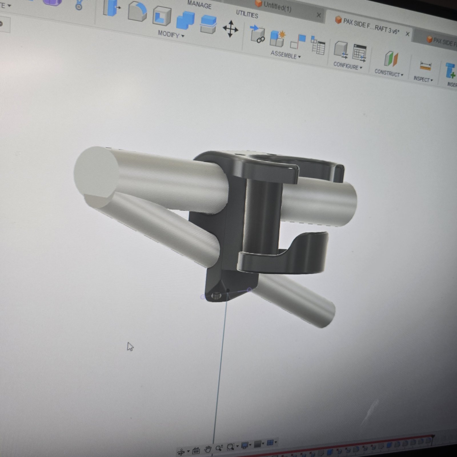
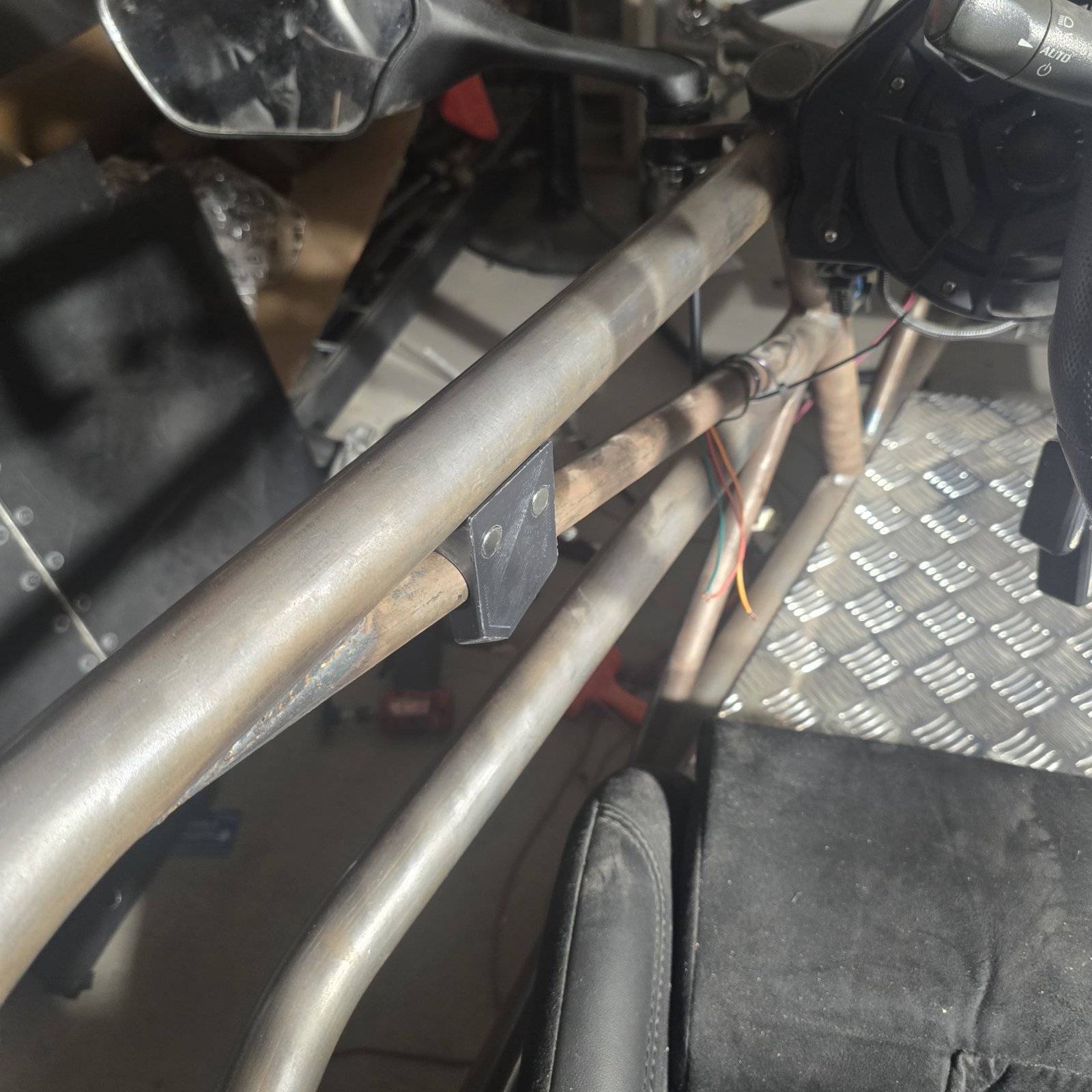
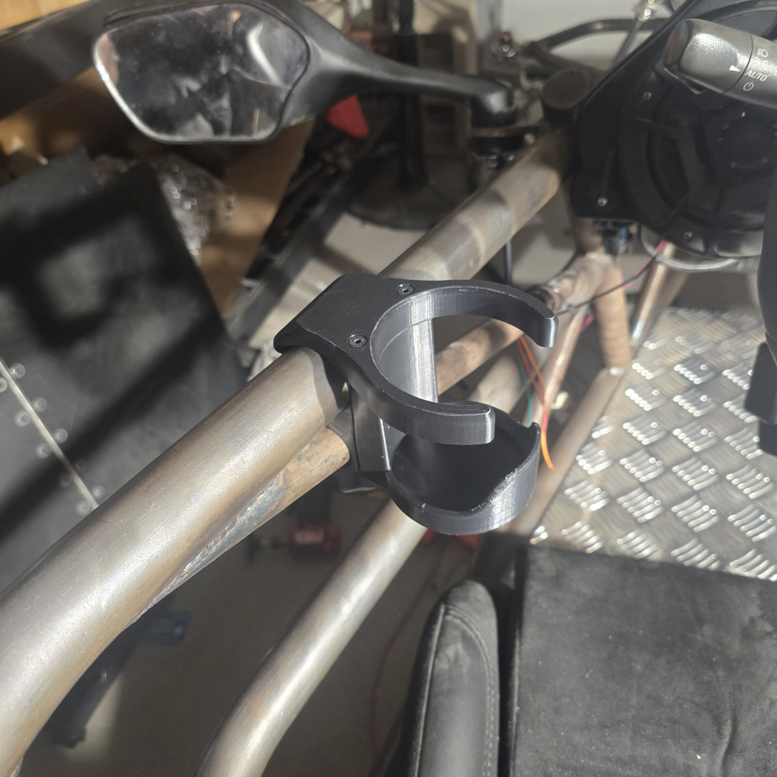
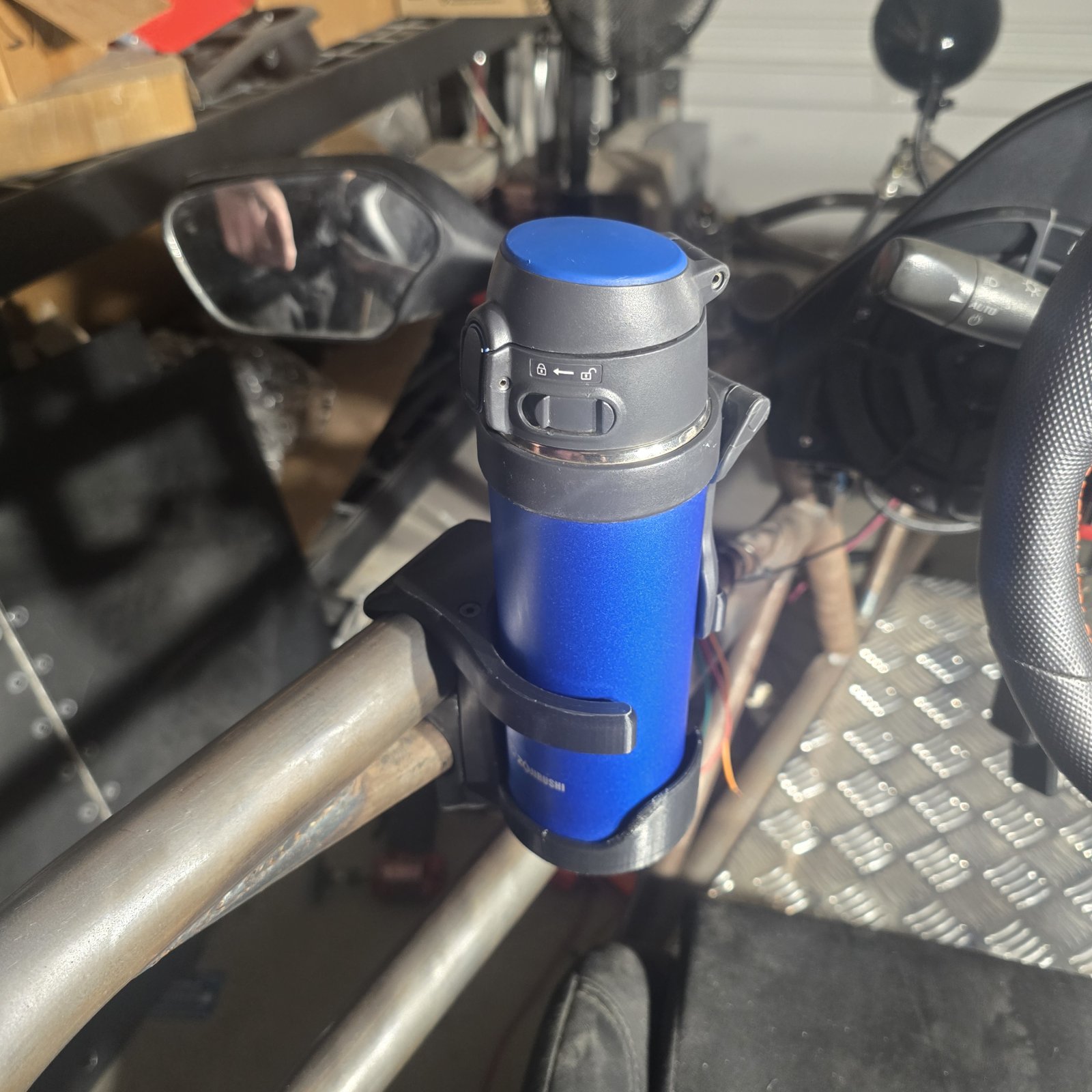
I wanted a cupholder because I plan to drive this to work regularly and coffee is part of my morning survival. I decided to design magnetic removable cupholders that mount on the side rails, with a housing that also incorporates the hidden LED focused beam to illuminate the seat when the courtesy light circuit is active. I was skeptical, but I like the position of the cupholder. My coffee cup is in reach with the shoulder harness fully tightened and can be utilized without taking my eyes off the road. Now I am just waiting on the LED bulbs, and a hole punch to prepare the neoprene rubber strip for the floorboard isolation.
1000066764.jpg
1000066769.jpg
1000066790.jpg
1000066812.jpg
1000066813.jpg
1000066814.jpg


Once I get the floorboard properly installed, I will install my new center console and then do a complete and final electrical test of all of the interior and dash circuits. After that, I plan to move to the engine compartment and finish the remaining wiring there, as well as mock up all of the plumbing and install/design mounts for the intercooler pump, coolant reservoir, oil vapor recirculation, ect. Still debating on whether I want to run the stock subframe or purchase the DF Goblin one.

 
Brian74
I've been wanting to get these **** floor panels solid mounted forever. Knocked that out today. CAD designed and 3D printed up a punch spacing guide, then measured and drilled the holes. The floor panels are isolated with 1/8" neoprene rubber strips, and sandwiched on top with neoprene washers. They shouldn't vibrate at all. I installed rivet nuts in the square tubing for mounting them... 3 forward and 3 aft. Tomorrow I will probably install the center console and hook up all of the electrical and run the subwoofer through a few frequencies to verify that the floorboards no longer audibly resonate.
1000066846.jpg
1000066848.jpg
1000066850.jpg
1000066851.jpg
1000066853.jpg
 
Brian74
Spent the last several days reading through forum posts and watching build videos to determine what additional work and parts are needed. It was a lot of digging and searching, but worth the time & effort. This made the remainder of the build a bit less intimidating as I was able to make some fair determinations, future plans and answer numerous questions I still had. With this crate engine, I will need to buy all of the cooling hoses (which I would have likely done anyways). Many of the lines are obsolete parts now so I will have to do some mixing and matching. Got the engine coolant and fuel lines mostly figured out. Verified that I hooked up all of the AIM dash connections with their customer service (which is excellent). Found a very reasonable local powder coater. Went to order some of the remaining parts and found out Rockauto no longer delivers to Arizona... Great.

I will finish the engine cooling line mock up, make my own AN6 fuel lines, and start intercooler liquid cooling line mockups next. I may also mock up the rear drivetrain to determine I have the all of the proper hardware and sizes. I then plan to tear the frame down and send parts off to powder coat. With the frame gone, that will give me some room to reorganize. I still need to figure out a rear wing, front spoiler, wheels & tires, and how to mount the aluminum side panels. I will likely purchase the tubular subframe from DF.

Eventually I need to uncrate this 1200W laser cutting table/welder that showed up and get it running.

20251119_101701.jpg
 
Brian74
Trying to figure out how I want to mount the side panels while I wait for parts. I didn't want to use rivets or rivet nuts because I want them to be removable and minimize any vibration and metal to metal contact with the frame. I decided to design and 3D print some brackets to use 3/4 velcro straps. The side panel will "float" 6mm out from the frame, which looks much better. I will fill the existing mount holes, which will give them a perfectly flat surface to vinyl wrap. I made the mounts exactly 2" long, which should make it easy to use 2" 3M VHB tape to adhere the mounts to the panels. With how light these panels are, the VHB tape will hold up just fine.

20251208_182657.jpg
 
Rauq
I 3d printed a set of these for installation in various spots to hold the side panels. I printed in PETG because that was my go-to at the time, although I've since been using more PC. Not sure if PC would be better for this application, but my research did tell me I probably needed a surface activator/prep/primer to get VHB to really stick to PETG, so that's what I did. Just cleaned the inside of the aluminum panels with iso ahead of install as well. All of the clamps were designed and printed for it, but only some of them actually got zip ties installed through the channel. Each clamp has about a 2"x2" surface, so they each got two strips of 1" wide and 2" long VHB on them. I've done decent triple digit speeds and hot and cold weather and they've held up for over a year.
54879
 
Brian74
I 3d printed a set of these for installation in various spots to hold the side panels. I printed in PETG because that was my go-to at the time, although I've since been using more PC. Not sure if PC would be better for this application, but my research did tell me I probably needed a surface activator/prep/primer to get VHB to really stick to PETG, so that's what I did. Just cleaned the inside of the aluminum panels with iso ahead of install as well. All of the clamps were designed and printed for it, but only some of them actually got zip ties installed through the channel. Each clamp has about a 2"x2" surface, so they each got two strips of 1" wide and 2" long VHB on them. I've done decent triple digit speeds and hot and cold weather and they've held up for over a year.
View attachment 54879
Thanks for the info; that's good to know. I will be using ASA. Probably going to use 10-12 on each panel which should distribute the load evenly and sheer load overkill assuming the VHB sticks well. VHB certainly seems like an easier decision than panel bond in terms of ease of install. I originally had a design similar to yours, but decided on a wedge shape to eliminate possibility of breakage and provide more clearance for some of the other clamps and components I am using in close proximity. I will try a test fit this weekend.
 
Rauq
FYI- I think in my testing, a chord of about 75% the ID of the clamp/OD of the tube was ideal for being able to press the clamp onto the tube without cracking the printed part but still maximizing hold on the frame tube. I measured 37.9mm OD on a tube and my clamp design has an opening of 28.425mm.
 
Brian74
FYI- I think in my testing, a chord of about 75% the ID of the clamp/OD of the tube was ideal for being able to press the clamp onto the tube without cracking the printed part but still maximizing hold on the frame tube. I measured 37.9mm OD on a tube and my clamp design has an opening of 28.425mm.

As a rule of thumb I use 75% on all of my other clamps (270 degrees) so sounds like we're on the same page.
 
Brian74
Going back to my original front spoiler design. I will run aluminum L brackets forward, with bushing pivot mounts. Slightly aft will be 3/4" rod with adjustable turnbuckes to change the angle of attack. I am happy with this configuration because it will allow me to fully change the spoiler design later on if needed. I 3D printed up the first draft of the gussets. Will test fit with the radiator, cowling, and hoses in place.

20251213_162057.jpg
20251213_162108.jpg
20251213_162115.jpg
20251213_154730.jpg
20251213_154422.jpg
20251213_162436.jpg
 
Brian74
Not a super productive day today, but did resolve all coolant plumbing issues. I got the fwd lower coolant hose and tee fitting in place. Then I took a mental snapshot of all the cooling lines, made a list, and brought all of the line fittings over to the auto parts store. They let me rummage the back aisle for the hoses I needed. I came home and test fit the stuff I bought and found that it all fits very well. Will need to do a little trimming but these hoses are actually a better fit than the ones DF recommends.

I am using the upper hose junction to add a fill cap. I took some measurements and quickly CAD designed a support bracket that will hold the fill port up high. It is currently printing in ASA.

My surge tank is Arizona dry rotted. Instead of trying to source another GM tank, I bought the ZZP tank, as it is metal, powdercoated, and has a low coolant level switch built in. I will design a proper mount for it.

20251214_130955.jpg
20251214_131009.jpg
20251214_131228.jpg
20251214_134413.jpg
20251214_133019.jpg
20251214_180026.jpg
20251214_180032.jpg

20251214_175947.jpg
 
David
Not a super productive day today, but did resolve all coolant plumbing issues. I got the fwd lower coolant hose and tee fitting in place. Then I took a mental snapshot of all the cooling lines, made a list, and brought all of the line fittings over to the auto parts store. They let me rummage the back aisle for the hoses I needed. I came home and test fit the stuff I bought and found that it all fits very well. Will need to do a little trimming but these hoses are actually a better fit than the ones DF recommends.

I am using the upper hose junction to add a fill cap. I took some measurements and quickly CAD designed a support bracket that will hold the fill port up high. It is currently printing in ASA.

My surge tank is Arizona dry rotted. Instead of trying to source another GM tank, I bought the ZZP tank, as it is metal, powdercoated, and has a low coolant level switch built in. I will design a proper mount for it.

View attachment 54912View attachment 54913View attachment 54914View attachment 54915View attachment 54916View attachment 54917View attachment 54918
View attachment 54919
How do you like the ZZP expansion tank? I was going to get it but one of things I found weird is the sight glass is almost at the top. Tank should be half full not completely filled if im not mistaken. Also didn't like that the lower hose connection was a nipple not AN capable. It sure does like gorgeous.

Is that low water sensor removable? I wonder if they sell a replacement. I would like to add that do the tank im building.
 
Brian74
How do you like the ZZP expansion tank? I was going to get it but one of things I found weird is the sight glass is almost at the top. Tank should be half full not completely filled if im not mistaken. Also didn't like that the lower hose connection was a nipple not AN capable. It sure does like gorgeous.

Is that low water sensor removable? I wonder if they sell a replacement. I would like to add that do the tank im building.

Sensor is removable, although I don't know if they sell a replacement. Looks like its just epoxied into the fitting. Those sensors rarely fail so not terribly worried. I am not thrilled with the sight glass either, but overall its a nice solid and well-built piece. Mounting will be fun to figure out. I wll probably build an L bracket out of steel and then CAD design and 3D print the bracket casing.
 
Brian74
Got the coolant fill bracket done, but it may be too high, so I may modify the design lower slightly.

Got the aft cowling on and tried to find a good position for the zzp surge tank. I have 6" speakers in my aft cowling, so not a lot of room. Got the tank positioned and made some measurements. Measured the tank and drew up a quick CAD draft of everything. I will weld a couple more mount brackets to the cross tube for strength. I set up a metal bracket with a 3D printed base, complete with a fastening/retaining strap to secure the tank.

I made the bracket fully bolt-on and height adjustable by 40mm, so I can adjust it slightly for cowling clearance or to tweak the tank water level line if needed. I will probably 3D print the brackets first and do a functional mockup to check the fit.

If anyone knows the actual angle of that surge tank bracket welded to the frame in relation to the horizon, I'd love to know for sure. With the car on jackstands it is hard to tell, but looks like they are canted about 16 degrees from straight vertical. (Just helps knowing so I can get the tank more level)

20251217_195435.jpg
20251217_195625.jpg
20251217_195510.jpg

20251217_200704.jpg
 
Last edited:
David
Got the coolant fill bracket done, but it may be too high, so I may modify the design lower slightly.

Got the aft cowling on and tried to find a good position for the zzp surge tank. I have 6" speakers in my aft cowling, so not a lot of room. Got the tank positioned and made some measurements. Measured the tank and drew up a quick CAD draft of everything. I will weld a couple more mount brackets to the cross tube for strength. I set up a metal bracket with a 3D printed base, complete with a fastening/retaining strap to secure the tank.

I made the bracket fully bolt-on and height adjustable by 40mm, so I can adjust it slightly for cowling clearance or to tweak the tank water level line if needed. I will probably 3D print the brackets first and do a functional mockup to check the fit.

View attachment 54948View attachment 54950View attachment 54951
View attachment 54953
Looking good, FYI I emailed ZZP regarding the coolant level sensor. I told them I had a broken sensor how can I get one. They weren't no help and asked me for a receipt and pictures. Seems like you can buy the sensors for replacement.
 
Brian74
I
Looking good, FYI I emailed ZZP regarding the coolant level sensor. I told them I had a broken sensor how can I get one. They weren't no help and asked me for a receipt and pictures. Seems like you can buy the sensors for replacement.

Good to know. Looks easy enough to just make a new one as well. Personally, I am not a big fan of their customer service. In the past its been pretty hit or miss, depending on who I talked to.
 
David
I


Good to know. Looks easy enough to just make a new one as well. Personally, I am not a big fan of their customer service. In the past its been pretty hit or miss, depending on who I talked to.
Yea I been trying to find a way to add coolant sensors to the tanks I will be making. I believe majority of the coolant level sensors work on resistance on/off switch type of sensor. Snice expansion tank has ro be half full I would weld a bung and like lower then half and try to wire up a sensor some how.
 
Brian74
Yea I been trying to find a way to add coolant sensors to the tanks I will be making. I believe majority of the coolant level sensors work on resistance on/off switch type of sensor. Snice expansion tank has ro be half full I would weld a bung and like lower then half and try to wire up a sensor some how.

In this case it is a purely a grounding switch, which leaves numerous options for sensors. It just goes to the BCM, which converts the ground signal to digital logic through the low speed data bus to the cluster.

Screenshot_20251218_084535_Chrome.jpg
 
David
In this case it is a purely a grounding switch, which leaves numerous options for sensors. It just goes to the BCM, which converts the ground signal to digital logic through the low speed data bus to the cluster.

View attachment 54959

Nice, not to bad to connect to the existing harness. I need to find a level switch the works the same way and I can screw into a bung.
 
Brian74
Spent the day trying to get my front spoiler design finalized. This will have up to 25 degrees of adjustability, while only losing 1/4" of ground clearance. All pivot points use nylon bushings to prevent galvanic corrosion. Lower airfoil is 3D printed and mounted using heat set inserts. With this mounting design, I can change to a different spoiler later on if need be. The only difference between the rendering and final product will be flush mount rivets at the pivot bracket supports.

5RAD SUPPORT v24.png
3RAD SUPPORT v24.png
4RAD SUPPORT v24.png
2RAD SUPPORT v24.png
1RAD SUPPORT v24.png
 
Back
Top