• We've upgraded and reskinned the forum. Notice something off? Email us at [email protected] and we'll fix it.

V1 Sluggonaut's Extended Track #364 - 2007 SS/SC (Turbo) Donor

Sluggonaut
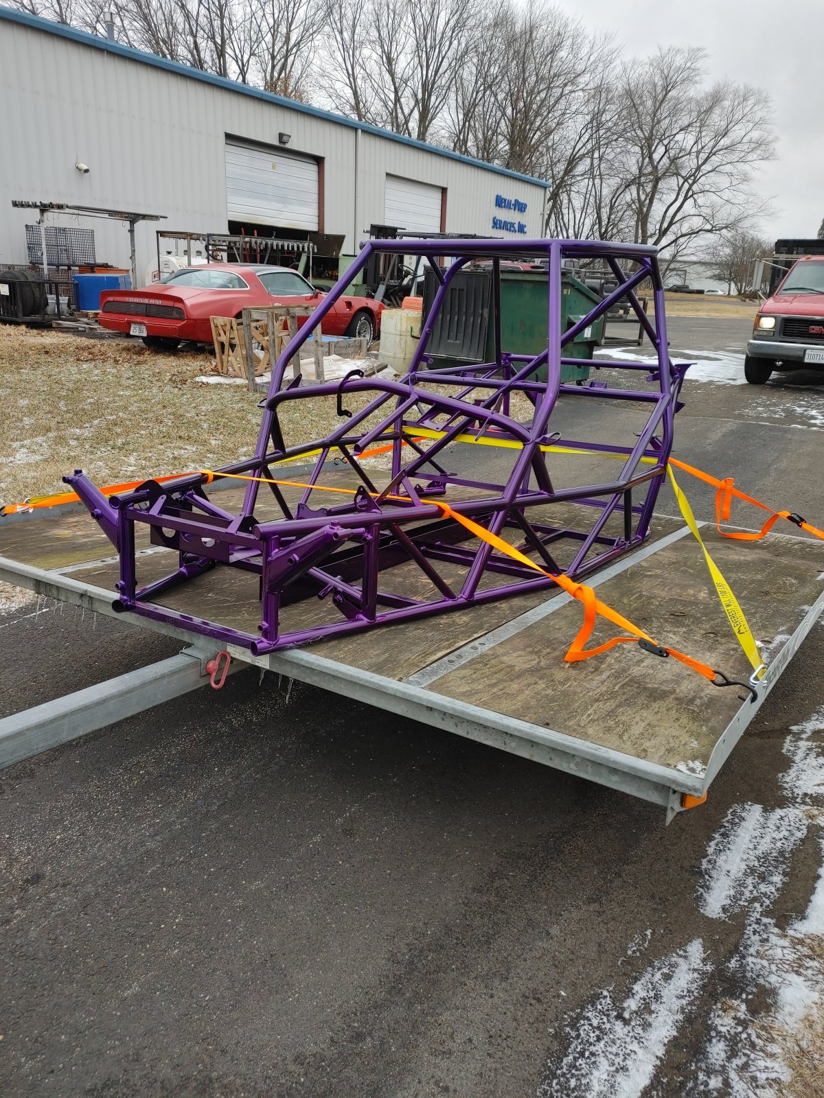
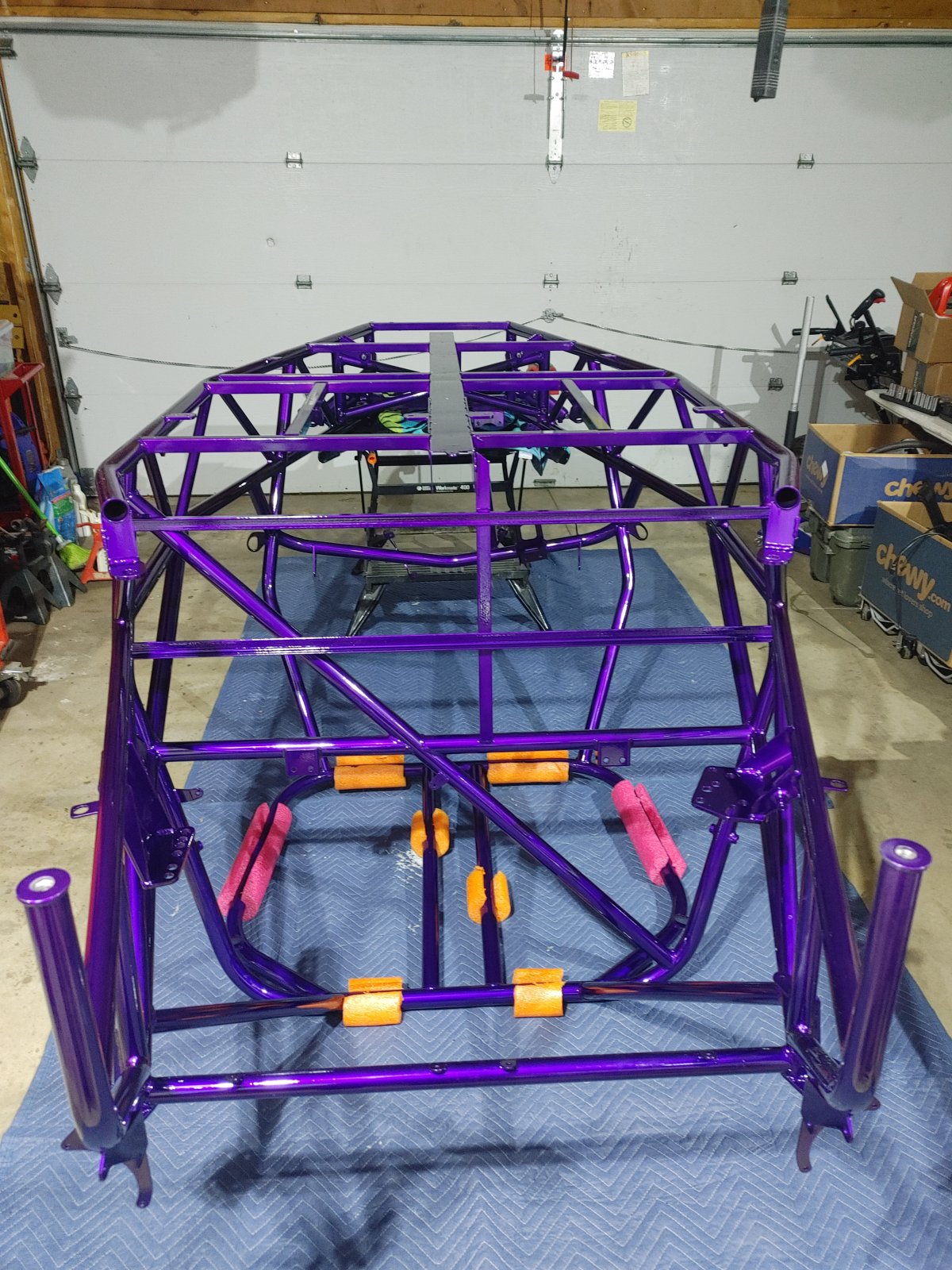
Got the freshly-coated parts home and in the garage. I found some help to get her turtled and ready for Build Day 1 tomorrow.
30916


30917
 
Sluggonaut
Build Day 1 is finally here. I was going to start tomorrow but my son stopped by so I used his help to get the hoses pulled.

The first one went in without an issue. The second was going fine until the hose was about 6" from the end and the hose ripped. Fortunately, his buddy was with him and they pulled on the hose while I secured the frame and we got it out. We trimmed a little too much off the end of the hose to get the ring started and it ripped right under the zip-tied section. We were able to get it zip-tied back up without losing any more length than the half-inch that ripped off. It went in just fine on the 2nd try.

It's pretty cold in the garage so I may be waiting until the morning to get the floor installed, but it's nice to have the hoses done as I was not sure how that was going to go.

30924
30925
 
Sluggonaut
I've only been able to get an hour in here and there over the weekend due to a wedding and some other plans. I was also able to get an hour in after work tonight.

So far the urethane adhesive was the biggest PITA, I managed to get that stuff everywhere and it's not easy to clean up. Everything else has been fairly straightforward and I'm so glad I ordered a replacement steering shaft as the donor's did not work - the new one went in without a hitch.

I called it a night after getting the pedal box installed. I think I'll be able to knock out quite a few more videos throughout the week with warmer weather coming our way this weekend. I'll get the valve cover back on the motor and get it cleaned up in anticipation of getting it installed in the near future. I'm not touching anything on the motor until after the first start because it ran fine before I stripped it. I have a laundry list of things I'd like to do after I get it running in the Goblin.


30958
 
Sluggonaut
After reading several build logs, I was well aware of the clutch pedal/steering shaft interference issue. Because I have an early model clutch pedal, I was also aware of the trimming I needed to do to the pedal, so I thought I was well-prepared for this next step.

What I wasn't prepared for is the amount of interference still present even after aggressive trimming of the switch landing pad.

I know many other builders have found success with a little trimming of the pedal and bending of the bracket, but the amount of interference I'm seeing will require more than a "little" of both - is this the same amount others have had to overcome?

The edge of the switch is already overhanging the platform I left intact- so I ran out of trimming real estate:
30972


I expected the switch pad to be hitting, but I wasn't aware I would need to remove so much of the pedal arm to make this clear - how much can be removed before the pedal arm is no longer structurally sound? Or do I need to bend the hell out of the bracket?
30973
 
Desert Sasqwatch
Look at the position of the EPS box and try to position the steering wheel shaft - one facing the seat - toward the outside of the car. This in turn will move the steering shaft going forward more toward the center of the car, away from the clutch pedal arm.
 
Ross
I did a fair amount of bending the clutch pedal mount, to move it away from the steering column. Loosen the steering column bolts & steering rack bolts and slide that as far as the mounts will allow.
 
Sluggonaut
I shimmed the top and outside EPS bolts with a handful of washers to move the steering wheel side outboard and shift the steering rack side inboard per DS' advice.

The steering shaft is well clear of the clutch pedal now. I didn't need to cut off as much of the switch pad as I did but I think it will be fine. I didn't have to bend the brackets either and I have plenty of room now. We'll see what downstream impacts this has later as we add more parts.
 
Desert Sasqwatch
You can reinforce the switch pad with some JB Weld if there is any doubt for integrity. ;) Also, check the clearance of the u-joint on the steering shaft where it goes through the firewall. Moving things in one place can make an issue in another.
 
Sluggonaut
Also, check the clearance of the u-joint on the steering shaft where it goes through the firewall. Moving things in one place can make an issue in another.

Clearance is probably better now than it was before - it's pretty much centered in the bulkhead opening now:

30981


To better document the 'Squatch method, here is what I did:

I loosened the EPS mounting bolts and moved the EPS unit around to see how different positions affected the steering shaft angle relative to the clutch pedal. Once I found the desired effect, I eyeballed the distance between the mount and the EPS to figure out how many washers I needed. I used washers to shim both the outboard bolt hole and the top/center bolt hole. Surprisingly, moving the top/center of the bracket had as much, if not more, of an effect than the outboard one.

Here is the mount from both sides - you can see how much the top/center is shimmed in these left and right side shots:

30982
30983


Here is the switch pad and clutch pedal clearance before and after:

30985
30986


30987
30988


I should have a better idea of how this affects the aesthetics in the near future, as this could impact steering wheel location (facing more outboard, slightly higher, and 3/8" away from the driver's seat) but I don't think it will be significant.

I did not need to bend the bracket at all. I followed the assembly video to cut down the side and backside of the switch pad and still had quite a bit of interference when I tried to install the clutch pedal assembly.

I did have to drill out the holes on the front of the clutch, as the bolts supplied in the kit did not fit through the holes. I thought it wasn't lined up at first but when I pulled it back off and checked, the holes were a touch too small - it wasn't binding, it just wasn't able to go through.

On the EPS, I had to use a longer bolt for the top/center hole. The next step up from the factory bolt (M6x1.0 x 16mm) that I could find at Home Depot was M6x1.0 x 30mm. It's a little long but the bolt hole is open in the back so it works fine. If a 25mm could be located it would be perfect. I didn't need one for the outboard side but I think I will install one for peace of mind.

# Clutch Pedal, Clutch Pedal Clearance, Clutch and Steering Shaft, Steering shaft to clutch pedal clearance
 
Desert Sasqwatch
Keep in mind when sitting in the car you are angled in toward the center of the car, not straight forward. So having the steering wheel angled a few degrees outward points it more directly at the driver's seat. AND putting a slight angle inward on the seat would also make for a more relaxed position.
If the steering wheel is positioned too high, swimming the entire EPS box lower - without changing its relative angle - can help put it into a more natural driver's position.
It's your Goblin, tweak it so it fits you...which also keeps others from driving it. ;):cool:
 
Sluggonaut
...putting a slight angle inward on the seat would also make for a more relaxed position.

I have the DF seat brackets so there's not much wiggle room for adjustment and I'm already powder coated so the seats are what they are...lol

Build progress is moving steadily along at 1-2 hours each night. I got through a few more videos tonight along with re-doing a few steps. A 5/8" coated clamp where it should have been a 3/8", a washer under a socket head bolt that interfered with the brake booster, and a few other minor things also got re-done. I even vacuumed out all the crud from drilling out the clutch bracket only to have to drill out my ground lugs.

After removing the ground nuts and washers that got powder coated to the frame, I took a wire wheel to the base of the bolt and found some new hardware to get the drilled-out ground lugs bolted up.

I got the wiring harness zip-tied into place only to find that just one of my 4 brake/clutch connectors actually reached where they needed to go, so I called it a night. I'll start tomorrow's session off by cutting open the harness to get those wires connected. I'll probably not tape anything back up until I get everything connected - this probably won't be my last wire length issue.

It felt pretty good to dig the harness out of the basement. I finished it right before Christmas and haven't seen it since I stashed it away for safekeeping. It seems like forever while waiting for your kit, then waiting for powder coating, and then the build finally starts. Compared to the wiring harness, the build videos fly by and the car starts taking shape quickly.
 
Rauq
I think you have the ESP bracket on backwards that’s why you had to shim it. I’ll double check when I get home.

Confirmed (also not final wiring install, just the first best picture I could find). It looks like you had it on in this orientation at one point so I'm not sure if you flipped it to allow for shimming, but I don't recall having to shave too too much off the clutch pedal arm or the front firewall.

31022
 
Sluggonaut
Mine is installed the same as Rauq's above.

When I first started the install I had one bolt in with it facing the other way, but quickly noticed it was backward compared to the video.

The curved edge of the bracket is towards the rear of the car in all my pics.
 
Sluggonaut
...I don't recall having to shave too too much off the clutch pedal arm or the front firewall.

Shimming the EPS moved the steering shaft toward the center of the car and it actually lined up in the firewall better than before shimming it. I didn't have to touch the firewall or the clutch pedal arm after shimming.

I cut the sensor pad before I tried to install it because I was following the videos. I don't think that was even necessary if I had shimmed the EPS first.
 
Sluggonaut
Took advantage of the warm weather today and painted the horn bracket and parking brake assembly. I also got up to the storage unit to bring the motor and trans home so I can start prepping it before I get to that part of the build.

I labeled everything pretty well during tear down because I was worried about getting everything plugged in correctly. However, I now realize I need to start reading up on the dual-pass, option B, and other plumbing as there seems to be a lot more plumbing than I remember when I plucked this thing a couple of months back.
 
Sluggonaut
I installed the radiator tonight and was going to finish up the wiring but had to stop before I cut any wires.

I've been following the build videos and the only wires I have in the front are the horn (connected) and driver-side headlight bundle on the driver-side, and three wires to the passenger side: passenger headlight bundle, the thick red cable with the plastic connector, and a pair of wires taped together (light blue and black). The light blue and black pair had quite a bit of length and I started unwrapping them to move the light blue wire closer to the power side of the radiator fan. After I unwrapped quite a bit, I stopped before cutting it because it dawned on me that because it also had a ground wire, it was likely the heat exchanger fan wire.

Even though this wire was the same color as the one in the video, there was only a single wire for the radiator fan in the video. Before heading inside to research, I went on to the next video and installed the gas tank. While I was back there, I found a blue wire labeled Radiator Fan with a connector already on it. Remembering this from early in the harness videos I stopped and went inside to figure this out.

So far, my research has been re-watching the wiring videos, and the Radiator Fan wire with the spade connectors is supposed to be by the fuse box according to the "DF Goblin Wiring Harness Guide Part 7 - Organizing the Main Harness, Pt. 4". Twelve seconds into that video the light blue radiator fan wire has the connector installed.

In watching "DF Goblin Wiring Harness Guide Part 11 - Finishing the Harness" the heat exchanger fan wire is taped up with a ground wire just after the 6:00 mark; however, the wire is pink in the video. I may have taped a ground to the radiator fan wire instead of the heat exchanger wire that should be pink. If that's the case, it's not a big deal and I can just wire that into the radiator fan. I don't need to know where the heat exchanger wire is because I'll be running just the NACA ducts for now. I do have extra power wires available later if needed for the HE fan.

I guess my question is, how do I know the light blue wire is the one I need? Do I just run a 10' length of wire from the wire in front to the back where the radiator fan wire is so I can check continuity? What wire do we attach to the other half of the spade connector on the radiator fan wire by the fusebox in the rear? I've watched all the videos and don't recall seeing how/where that connector gets connected.
 
R
I installed the radiator tonight and was going to finish up the wiring but had to stop before I cut any wires.

I've been following the build videos and the only wires I have in the front are the horn (connected) and driver-side headlight bundle on the driver-side, and three wires to the passenger side: passenger headlight bundle, the thick red cable with the plastic connector, and a pair of wires taped together (light blue and black). The light blue and black pair had quite a bit of length and I started unwrapping them to move the light blue wire closer to the power side of the radiator fan. After I unwrapped quite a bit, I stopped before cutting it because it dawned on me that because it also had a ground wire, it was likely the heat exchanger fan wire.

Even though this wire was the same color as the one in the video, there was only a single wire for the radiator fan in the video. Before heading inside to research, I went on to the next video and installed the gas tank. While I was back there, I found a blue wire labeled Radiator Fan with a connector already on it. Remembering this from early in the harness videos I stopped and went inside to figure this out.

So far, my research has been re-watching the wiring videos, and the Radiator Fan wire with the spade connectors is supposed to be by the fuse box according to the "DF Goblin Wiring Harness Guide Part 7 - Organizing the Main Harness, Pt. 4". Twelve seconds into that video the light blue radiator fan wire has the connector installed.

In watching "DF Goblin Wiring Harness Guide Part 11 - Finishing the Harness" the heat exchanger fan wire is taped up with a ground wire just after the 6:00 mark; however, the wire is pink in the video. I may have taped a ground to the radiator fan wire instead of the heat exchanger wire that should be pink. If that's the case, it's not a big deal and I can just wire that into the radiator fan. I don't need to know where the heat exchanger wire is because I'll be running just the NACA ducts for now. I do have extra power wires available later if needed for the HE fan.

I guess my question is, how do I know the light blue wire is the one I need? Do I just run a 10' length of wire from the wire in front to the back where the radiator fan wire is so I can check continuity? What wire do we attach to the other half of the spade connector on the radiator fan wire by the fusebox in the rear? I've watched all the videos and don't recall seeing how/where that connector gets connected.
This is just my best guess as I haven’t started assembly yet:

the radiator connector originally is part of the engine harness. Most likely, the connector at the back in your harness will connect to that radiator fan wire on the engine harness.

To check if the wire up front is indeed for your radiator fan and not the HE fan, you’ll need to check continuity from that wire with the radiator fan connector you have at the back. If you have a tester, have someone hold a probe on the front wire you have and use the other to start touching the pins in the connector at the back and see if any of them show continuity. You may need to pull the harness to get the probes to reach each end.
 
Back
Top
