Benjy's Track Chassis #007 - 10 SS/TC donor

benjy

Well-Known Member
Progress seems to be cooking now :cool: Stage 2 and 3 arrived recently, now the only thing stopping progress is a full time job :rolleyes:

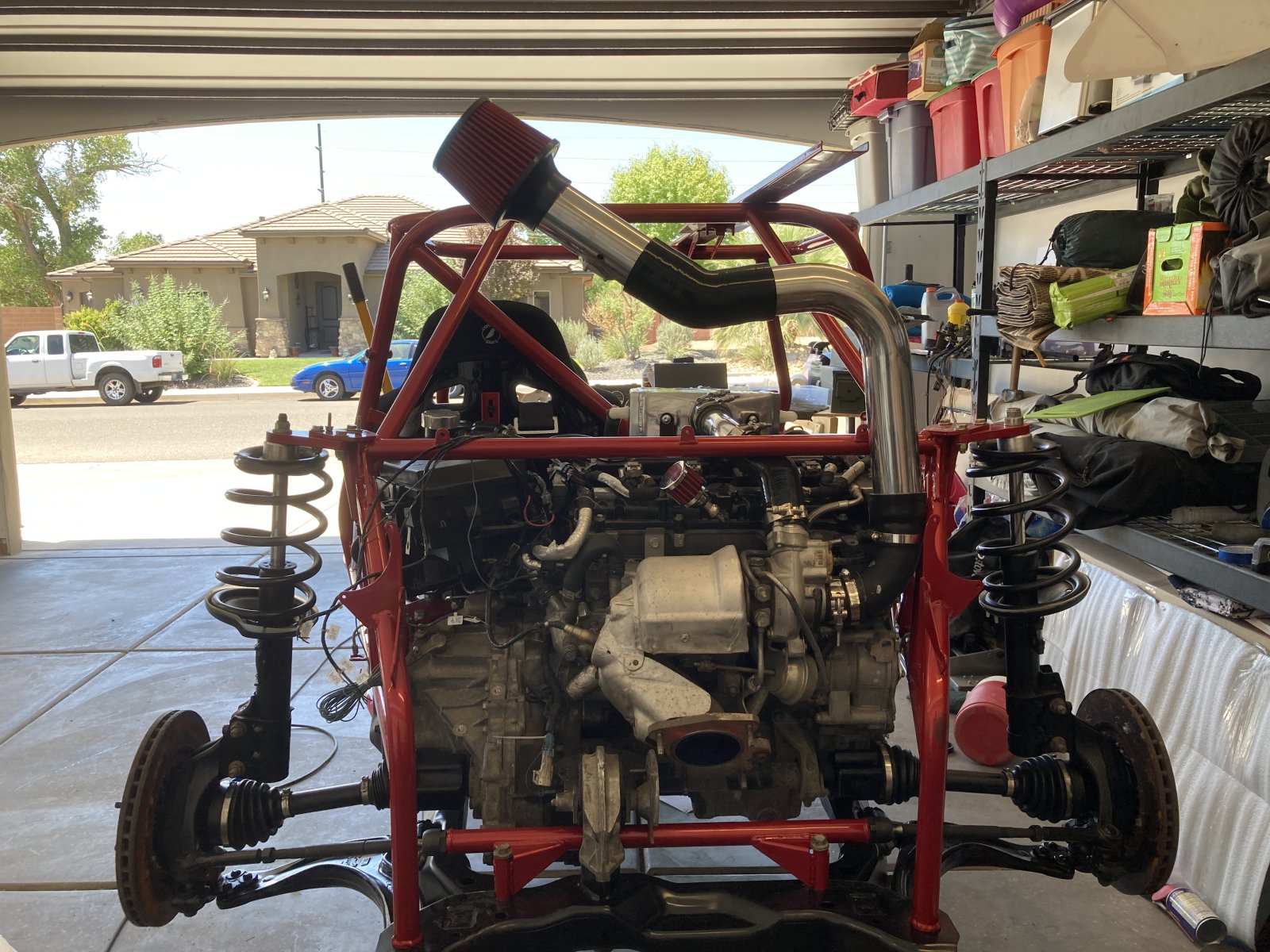
Brakes, shifter and wiring are on the short list. This weekend I hooked up the intercooler, heat exchanger and air intake.

I ordered a failsafe wideband afr/boost gauge. The “failsafe” function can trigger a shutoff in the event boost/afr falls outside a predefined range. I was initially thinking about cutting power to the ECM, but that seems like it could be dangerous/unwise. I don’t think it’s possible to easily kill boost on the LNF? I’m thinking I might just mount an idiot light unless someone has a better idea?

As I was messing around with the air filter location and had to tease my wife to see what she thought... gotta get those IAT’s down!!!

9D742C4F-4777-4438-8970-A0BE14E9BD28.jpeg
 

JBINTX

Goblin Guru
Benjy: Did you install the valve cover vent?
Or, is it left over from the donor and a previous owner?
 

benjy

Well-Known Member
Benjy: Did you install the valve cover vent?
Or, is it left over from the donor and a previous owner?
The filter was included with my kit parts. I just threw it on there a couple months ago and didn’t think about it again until hooking up the maf this weekend, and remembered it was designed to be routed to the intake.
 

JBINTX

Goblin Guru
The filter was included with my kit parts. I just threw it on there a couple months ago and didn’t think about it again until hooking up the maf this weekend, and remembered it was designed to be routed to the intake.
Maybe I was not precise enough. I was inquiring about the little 3" filter on the back side of the valve cover.
 

benjy

Well-Known Member
In this week's edition of "I have know idea what all these vacuum/boost lines do..."

I think the only thing I removed when pulling the engine was the orange line to the turbo. So if everything was correct before, I'm not sure where the barb next to the MAP is supposed to be routed? The gray line not hooked up is my AFR gauge which will just be tee-d into wherever the brass barb is routed...

IMG-0366.jpg
 

benjy

Well-Known Member
Maybe I was not precise enough. I was inquiring about the little 3" filter on the back side of the valve cover.
Yup, that's the one I was talking about, that little filter was included in the pile of parts I purchased. Isn't that normally vented to the intake?
 

Ark :D

Goblin Guru
Yep, for me, that goes to the intake via a check valve. Not sure of the importance of the check valve (or if it's even necessary), but there was one there from the factory.
 

JBINTX

Goblin Guru
The engineers tried to design a system to keep a vacuum in the valve cover area. It is essential to help with the pressure build up in the crankcase, and ultimately actual power generation if the piston has to push against pressure on the down stroke.

The filter you have on there is not OEM. It will not keep vacuum in the valve cover. It is only a vent, as is.

If you wish to read further about your decision to leave it, here is a good thread. :)

https://dfkitcar.com/forum/index.php?threads/oil-separator.1596/
 

benjy

Well-Known Member
In this week's edition of "I have know idea what all these vacuum/boost lines do..."

I think the only thing I removed when pulling the engine was the orange line to the turbo. So if everything was correct before, I'm not sure where the barb next to the MAP is supposed to be routed? The gray line not hooked up is my AFR gauge which will just be tee-d into wherever the brass barb is routed...

View attachment 16156
I've been suspect of the "t" between the red/green/blue marked lines in the pic above, since they were using hose clamps, not the OEM clamps on the rest of the lines. I am fairly confident about a few things at this point... the red line needs to go to the brass barb next to the MAP. The "t" needs to be eliminated and just plumbed straight, and I will plumb my AFR/boost gauge vacuum line off of the brass barb to register boost. Amateur hour over here :)

vactank3.jpg
 

benjy

Well-Known Member
The engineers tried to design a system to keep a vacuum in the valve cover area. It is essential to help with the pressure build up in the crankcase, and ultimately actual power generation if the piston has to push against pressure on the down stroke.

The filter you have on there is not OEM. It will not keep vacuum in the valve cover. It is only a vent, as is.

If you wish to read further about your decision to leave it, here is a good thread. :)

https://dfkitcar.com/forum/index.php?threads/oil-separator.1596/
I appreciate your insight! After reading those threads, I'm going to be routing it back to the intake, and just run CRC or similar at oil change intervals.
 

benjy

Well-Known Member
Running the DF solstice calipers, what is everyone using for brake lines? I've read something about using an OE front brake line, and shaving a banjo bolt?

Or is everyone just running braided lines?
 

benjy

Well-Known Member
Thanks Ross, it made more sense once I started putting it together. I thought the old front hose was used on the front. But... as with most things you reuse the old rear hose on the front, and front hose can be reused on the back :)

Wheels arrived yesterday. Online pics make them appear very gold, but in person they are a very rich bronze color. Excited to get them mounted up!

022E6C00-2985-457B-98E1-6530FC934B62.jpeg


51DF7B1E-84E0-45AA-8EC0-6D7F645FCCDE.jpeg
 

PyroGuy923

Well-Known Member
Thanks Ross, it made more sense once I started putting it together. I thought the old front hose was used on the front. But... as with most things you reuse the old rear hose on the front, and front hose can be reused on the back :)

Wheels arrived yesterday. Online pics make them appear very gold, but in person they are a very rich bronze color. Excited to get them mounted up!

View attachment 16606

View attachment 16605
Looks good. I was just looking at those last night. Its between those and Cosmis XT-206R's in Hyper Bronze
 
Top