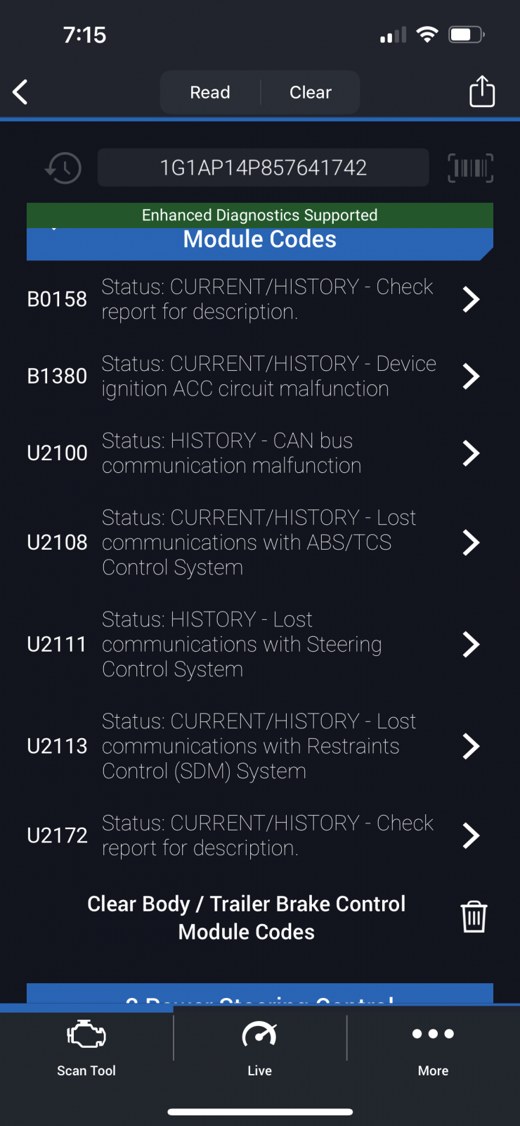
History: your car wasn't communicating on the GM high speed LAN.
ABS has been removed, so it won't be communicating.
SDM has been removed, so it won't be communicating.
B1380 seems like a big clue. Accessory circuit short? The key circuit is shown in the first image
here.
AllDataDIY
Login
After you log into AllDataDIY, you can find more info
here.
DTC B0158
CIRCUIT DESCRIPTION
The body control module (BCM) monitors the outside air temperature sensor to display outside air temperature. The temperature sensor is a 2-wire negative temperature co-efficient thermistor. The BCM applies
5 volts to an internal input resistor that is connected to the signal circuits of the Outside air temperature sensor. The BCM provides the ground to the outside air temperature sensor through the low reference circuit. The BCM monitors the voltage drop across the Outside air temperature sensor and uses the input for automatic control calculations. When the outside air temperatures are cold, the resistance of the sensors are high and the voltage signals are high. When the air temperatures are hot, the resistance of the sensors are low and the voltage signals are low. The BCM converts the voltage value to a temperature value of Celsius and Fahrenheit to be displayed by the driver information center (DIC).
DTC B1380
CIRCUIT DESCRIPTION
The body control module (BCM) monitors the ACCESSORY signal from the ignition switch. When the vehicle operator places the ignition switch in the Accessory or Run position, the switch supplies B+ to the BCM ACCESSORY input terminal. If this circuit becomes shorted to B+, ground or the circuit opens, DTC B1380 will set.
DTC U2172
CIRCUIT DESCRIPTION
Modules connected to the GMLAN serial data circuits monitor for serial data communications, during normal vehicle operation. Operating information and commands are exchanged among the modules. The modules have programmed information about what messages are needed to be exchanged on the serial data circuits, for each virtual network. The messages are also supervised and some periodic messages are used by the receiver module as an availability indication of the transmitter module. The supervision time-out period is
250 ms . Each message contains the identification number of the transmitter module. When a message that indicates the availability of the transmitter module is not received, the receiver module sets a DTC 21xx where xx is equal to the 2-digit identification number of the transmitter module.
The DTC descriptors listed below provide a method for determining which module is not communicating. A module with a GMLAN serial data circuit malfunction or which loses power during the current ignition cycle will have a Loss of Communication DTC set by other modules that depend on information from that failed module. The modules that can communicate will set a DTC indicating the module that cannot communicate.