-
We've upgraded and reskinned the forum. Notice something off? Email us at [email protected] and we'll fix it.
You are using an out of date browser. It may not display this or other websites correctly.
You should upgrade or use an alternative browser.
You should upgrade or use an alternative browser.

jirwin
Goblin Guru
- jirwin Goblin Guru
Figured I'd contribute something I'm using right now. It uses these p clamps you can get at HarborFreight or Amazon or where ever and is meant to mount an AEM Boost Solenoid. Uses some long small bolts (sorry can't remember size) to hold it on, and a short M10 allen headed bolt to hold it to the p clamp.


Attachments
Rauq
Goblin Guru
- Rauq Goblin Guru
Here's my 3d printed valve spring compressor tool. It uses 4 cam cap bolts and two M6 flange nuts from my donor hardware pile. I would not advocate that you run a cam cap bolt in and out 16 times here and then reuse it in the motor so you may want to use your own bolts, but the cam cap bolts are ideal for their length of engagement relative to the displacement needed to compress a spring far enough to remove and install the keepers.
The version pictured below is PETG, an earlier revision was PLA+ and while the cups had issues, the bridge did not. The bridge is printed with the
M6 flange nuts go in the bottom of the bridge. There are recessed hexes to keep the nuts from spinning. Friction pads go on the bottom of the extension bolts and are a pretty nice press fit. Caps sit on top of the retainers, and then extension bolts are run down. If you run out of threads, you've gone more than far enough. Unfortunately a completely uncompressed valvespring is long enough that it will still have a little spring pressure even with the extension bolts run all the way back out, but not so much that reinstallation is a pain.
A dab of assembly lube on the keeper grooves of the valve stem works wonders to get the keepers back in, and a dab of lube between the friction pads and the retainer cups keeps all the plastic happy.
From what I read, the intake and exhaust valves are canted at 16 and 18°, so this thing splits the difference at 17°. The angle offset didn't seem to make a difference. I did run one upgraded/stiffer valve spring all the way down by itself, but I would recommend running each pair of springs for a cylinder down a bit at a time each so as to not unnecessarily stress the part.
Ignore the nasty print, I had an issue early on before the introduction of the friction pads where the bolt head would end up going through the retainer cups. I tried a few different redesign/approaches, and one of them broke after I got only one keeper out of a retainer, so I ran this version again and added the friction pads. In my haste I didn't update my print settings for a material change, but it worked just fine, so here we are.
Attachments
")
LaunchPad
Well-Known Member
- LaunchPad Well-Known Member
Snice we kind of on the subject, does anyone have a 3d scanner? If so which one and how do you like it?
Im thinking in designing a dashboard with two screens and would be cool if I can 3d scan the dash area to create something.
i have a creality "scan lizard"- there is a learning curve for scanning that i haven't made a heck of a dent in and spread too thin currently to devote the necessary time. that said the first several scans I made of some ~3 inch tall ceramic objects my wife had sitting around were AWESOME. you could see the actual layers of glaze in the finished scans so the detail is certainly better than the 0.5mm they claim for me! i would post an image but i just now noticed the thumbdrive from my key chain is absent-grr
trying to get decent scans of an LS motors alternator so i could make full size PLA mockup parts for another project was eventually abandoned due to my poor progress on said learning curve. i invested in a motorized turn table that can do a full 380 pounds and chemistry set stands so i could hold the scanner and studio lights at various heights for other scans and invested in nearly every athletes foot pounder and scanning spray but the car parts just would not do the kind of quality i was looking for.
Keckster
Well-Known Member
LaunchPad
Well-Known Member
- LaunchPad Well-Known Member
On the way home from a cars and coffee i was dreaming up a snap-in windshield mount. . . .i have been follow a few folks on da youtube doing 3D printing of whole car bodies and a widebody kits and i suppose somewhat inspired. so i think i could best describe as a PVC tube type of profile cut so the PVC can snap over the roll cage frame directly with the addition of a frame for the plexi to be bonded to. . .sorta like-a-dis:

so take that profile and extrude along a path (technical CAD term lol) for the front part of the cage. i have some new filament inbound and will have to make in sections on the printer and glue together but it sure seems like it would work on at least first thought. inputs?
here is a sample of my first test piece. there will be changes i am sure. did this in FREECAD so anyone can do the same. corners on top and bottom will be addressed shortly.

test print#2 came out looking GREAT. . .but turns out the PLA+ or the design was a bit toooooo robust to push over the roll cage. that stuff is ?STRONG!! i use 8 walls and concentric layers with only 25% infill. this model needs to be adjusted for its stiffness as well as quite a bit more spacing on the "back" side such that it will clear the mounts for the instrument cluster. i might be able to have prototype test print 3 done by the evening.
so take that profile and extrude along a path (technical CAD term lol) for the front part of the cage. i have some new filament inbound and will have to make in sections on the printer and glue together but it sure seems like it would work on at least first thought. inputs?
here is a sample of my first test piece. there will be changes i am sure. did this in FREECAD so anyone can do the same. corners on top and bottom will be addressed shortly.
test print#2 came out looking GREAT. . .but turns out the PLA+ or the design was a bit toooooo robust to push over the roll cage. that stuff is ?STRONG!! i use 8 walls and concentric layers with only 25% infill. this model needs to be adjusted for its stiffness as well as quite a bit more spacing on the "back" side such that it will clear the mounts for the instrument cluster. i might be able to have prototype test print 3 done by the evening.
Attachments
Last edited:
LaunchPad
Well-Known Member
- LaunchPad Well-Known Member
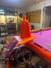
well i am on version 3 now for the windshield edge. taking about 4 hours per sample 4" piece to print. version 2 was a bit light on its natural clamping force. This one is much more beefy and has room for wire harness and can clear the instrument cluster brackets if trimmed. final version will not really need trimming. this is an iterative process. lol
for version #4 i have to have made to length for the windshield left and right sides with the holes for the threaded heat set nut rivets as well as indexing pin locators for eventually adding the corners.

for version #4 i have to have made to length for the windshield left and right sides with the holes for the threaded heat set nut rivets as well as indexing pin locators for eventually adding the corners.
Attachments
duthehustle93
Well-Known Member
- duthehustle93 Well-Known Member
Sure, I'll shoot you a PM.Anyone willing to help out with printing a few of these for me? I don't mind paying. Just don't have a printer and no experience in the process. I'm near Charleston, SC if that helps!
Similar threads
- Replies
- 212
- Views
- 49K