

-
We've upgraded and reskinned the forum. Notice something off? Email us at [email protected] and we'll fix it.
You are using an out of date browser. It may not display this or other websites correctly.
You should upgrade or use an alternative browser.
You should upgrade or use an alternative browser.
V1 Sluggonaut's Extended Track #364 - 2007 SS/SC (Turbo) Donor


Sluggonaut
Goblin Guru

- Sluggonaut Goblin Guru
I have about 7 samples I ordered but am not really excited about any of them. I may have to spend the money and get a design done. I was going to go with just a single color wrap and I liked quite a few of the color-shifting ones but no decision made yet.
On the E85 tune, it was supposedly mid-300s. Butt dyno said it was 300-ish, not sure about mid-300s.
On the E85 tune, it was supposedly mid-300s. Butt dyno said it was 300-ish, not sure about mid-300s.

Trail_Creeper
Well-Known Member

- Trail_Creeper Well-Known Member
Where did you order your wrap from?I have about 7 samples I ordered but am not really excited about any of them. I may have to spend the money and get a design done. I was going to go with just a single color wrap and I liked quite a few of the color-shifting ones but no decision made yet.
On the E85 tune, it was supposedly mid-300s. Butt dyno said it was 300-ish, not sure about mid-300s.

Desert Sasqwatch
Bigfoot Goblin

- Desert Sasqwatch Bigfoot Goblin
Gotta be something in green to do the full Goblin theme.

Sluggonaut
Goblin Guru
- Sluggonaut Goblin Guru
Where did you order your wrap from?
Amazon. 3x5" samples are like $2.50.
Sluggonaut
Goblin Guru
- Sluggonaut Goblin Guru
I'm assuming this piece is a mechanical boost controller, but how does it work exactly? Not how a boost controller works, but how this style functions with just the port on the end.
This is just sitting here for the pic to show the lines run to the wastegate on the K04. It was originally bolted to the firewall in the donor. I just thought mechanical boost controllers had a knob or something for the adjustment and this just has a Schrader valve type connection on the end.
All my searches for ZZP boost controllers show something along the lines of what I expected to see and not this, but hoping someone has seen this or can explain it.
I also have to assume it came with the ZZP entry-level turbo swap kit that is installed, I just can't find this part in anything related to that kit.
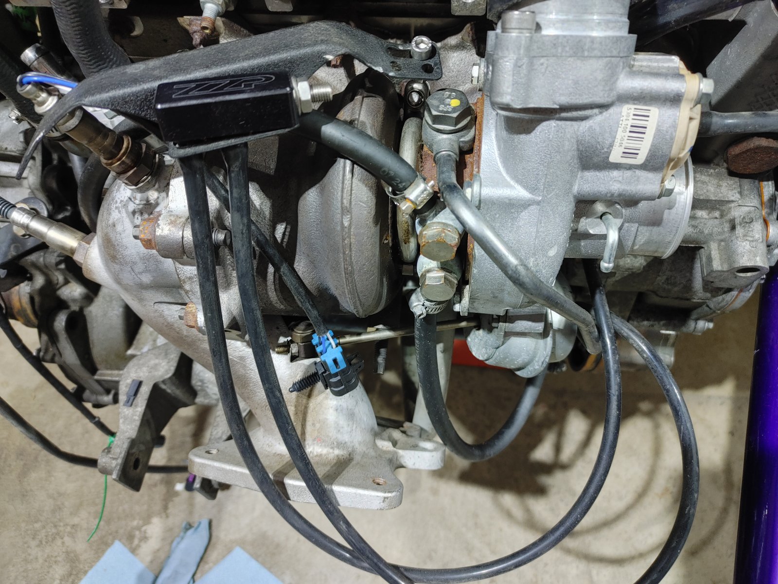
This is just sitting here for the pic to show the lines run to the wastegate on the K04. It was originally bolted to the firewall in the donor. I just thought mechanical boost controllers had a knob or something for the adjustment and this just has a Schrader valve type connection on the end.
All my searches for ZZP boost controllers show something along the lines of what I expected to see and not this, but hoping someone has seen this or can explain it.
I also have to assume it came with the ZZP entry-level turbo swap kit that is installed, I just can't find this part in anything related to that kit.


Trail_Creeper
Well-Known Member
- Trail_Creeper Well-Known Member

Sluggonaut
Goblin Guru
- Sluggonaut Goblin Guru
I believe it's just an allen head screw instead of a knob.
Thanks Nate!
I'll grab a light and my glasses and check again. It looked like a valve the last time I looked at it. lol
Sluggonaut
Goblin Guru
- Sluggonaut Goblin Guru
It is in fact just a long allen set screw. When I shine a light in the end, the reflection makes it looks like a Schrader valve. When you stick an allen wrench in there you feel like a complete idiot.
Sluggonaut
Goblin Guru
- Sluggonaut Goblin Guru
I believe the brass fitting that goes into the hole next to the MAF is supposed to run to the valve cover from other posts I've read, but if my donor didn't have anything coming from that pipe should I just plug the hole?
Does anyone know what this bracket is for? I have 2 of them. After painting all of the small bare steel parts these are the only ones that I don't remember which box/bag they came out of originally.
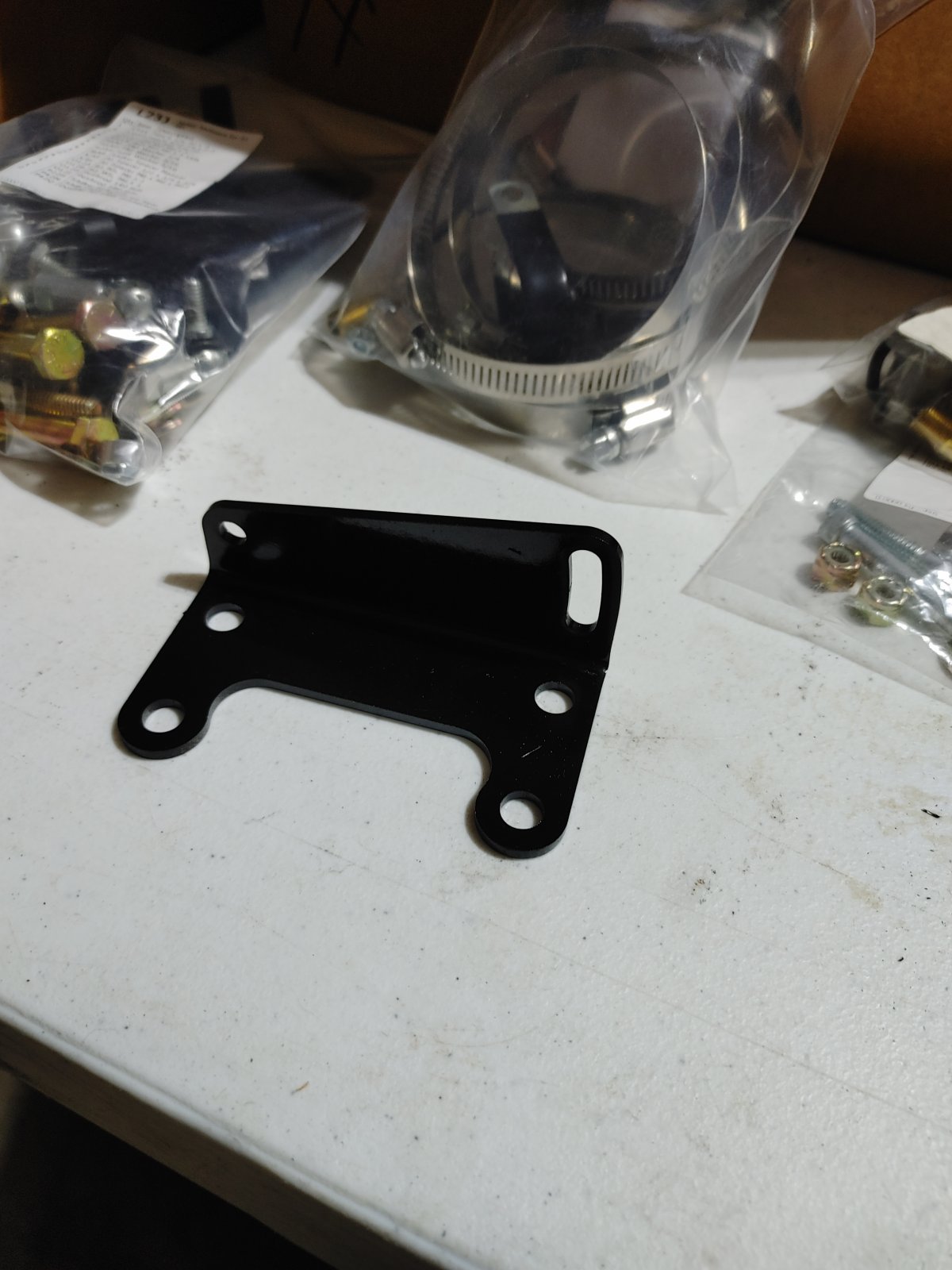
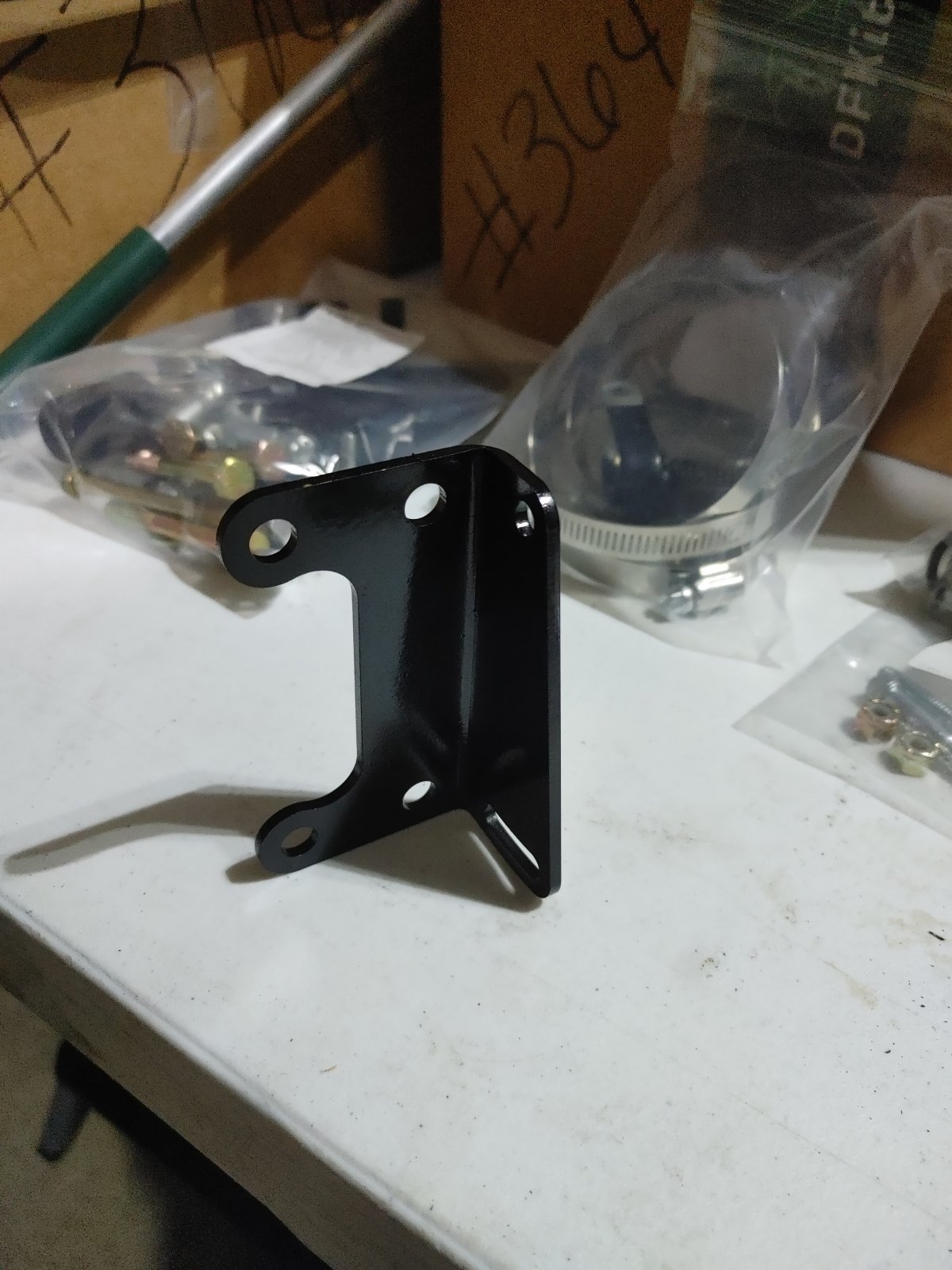
Does anyone know what this bracket is for? I have 2 of them. After painting all of the small bare steel parts these are the only ones that I don't remember which box/bag they came out of originally.
Sluggonaut
Goblin Guru
- Sluggonaut Goblin Guru
For those running the Option B tank, where are you running the clear plastic tube that was originally routed to the brass elbow on the top of the heat exchanger on the Cobalt?
I think I remember reading somewhere about running it to somewhere on the intake manifold, but I can't find that post now.
I think I remember reading somewhere about running it to somewhere on the intake manifold, but I can't find that post now.


- r3drckt Goblin Guru
Correct, those are the rear wing mounts that attach the top of the brackets to the wing.
Never cap the valve cover vent port/tube. This will create pressure inside the engine block that could cause blow by on your pistons and get oil into the combustion chamber. Worst case you can blow a gasket/seal somewhere that requires a rebuild, but I haven’t seen it throw a rod or anything. The vent tube is design to relieve the pressure build up in the engine, particularly in boosted applications where the pressure can get really high. If anything, run the connection to an oil catch can, then to the barb next to the MAF, or put a filter on the outlet barb to the atmosphere. The port on the intake next to the MAF would be the one to get plugged then to eliminate a vacuum leak.
Regarding the Option B, you would have to remove your intake, end plate, laminova cores, and then drill/tap the manifold at the top of the laminova turn around. To me, I didn’t want to tap this spot as it’s a permanent change and there is another option to do. The point of the Option B is to increase coolant capacity in the system and to relieve air out of the system. The factory configuration didn’t need the manifold tapped, so why does it need to be now is my thought. Air in a system goes to the highest point before it gets “stuck.” So what I’m going to do is place a T barb on the top line out of the end plate and have the top T go to the option B, the middle T go to the heat exchanger, the bottom T obviously to the end plate. Or if it’s placed on the horizontal line, middle barb is option B and side barbs are the lines to the heat exchanger and endplate. Just make sure the line is above the manifold at this point.
Never cap the valve cover vent port/tube. This will create pressure inside the engine block that could cause blow by on your pistons and get oil into the combustion chamber. Worst case you can blow a gasket/seal somewhere that requires a rebuild, but I haven’t seen it throw a rod or anything. The vent tube is design to relieve the pressure build up in the engine, particularly in boosted applications where the pressure can get really high. If anything, run the connection to an oil catch can, then to the barb next to the MAF, or put a filter on the outlet barb to the atmosphere. The port on the intake next to the MAF would be the one to get plugged then to eliminate a vacuum leak.
Regarding the Option B, you would have to remove your intake, end plate, laminova cores, and then drill/tap the manifold at the top of the laminova turn around. To me, I didn’t want to tap this spot as it’s a permanent change and there is another option to do. The point of the Option B is to increase coolant capacity in the system and to relieve air out of the system. The factory configuration didn’t need the manifold tapped, so why does it need to be now is my thought. Air in a system goes to the highest point before it gets “stuck.” So what I’m going to do is place a T barb on the top line out of the end plate and have the top T go to the option B, the middle T go to the heat exchanger, the bottom T obviously to the end plate. Or if it’s placed on the horizontal line, middle barb is option B and side barbs are the lines to the heat exchanger and endplate. Just make sure the line is above the manifold at this point.
Last edited:
Sluggonaut
Goblin Guru
- Sluggonaut Goblin Guru
Never cap the valve cover vent port/tube. This will create pressure inside the engine block that could cause blow by on your pistons and get oil into the combustion chamber. The vent tube is design to relieve the pressure build up in the engine, particularly in boosted applications where the pressure can get really high. If anything, run the connection to an oil catch can, then to the barb next to the MAF, or put a filter on the outlet barb to the atmosphere. The port on the intake next to the MAF would be the one to get plugged then to eliminate a vacuum leak.
Do you have a pic of which port it would be connected to? My current goal is to get everything installed just as it was on the donor to get through the first start and confirm my wiring harness and overall build works. If I need to modify how it is currently configured, I will do that after I achieve that first goal. The donor ran and performed great, so it's possible this has been addressed but my lack of knowledge/experience on this platform requires me to check by comparing mine to other examples. Especially since mine is far from stock.
Regarding the Option B, you would have to remove your intake, end plate, laminova cores, and then drill/tap the manifold at the top of the laminova turn around. To me, I didn’t want to tap this spot as it’s a permanent change and there is another option to do. The point of the Option B is to increase coolant capacity in the system and to relieve air out of the system. The factory configuration didn’t need the manifold tapped, so why does it need to be now is my thought. Air in a system goes to the highest point before it gets “stuck.” So what I’m going to do is place a T barb on the top line out of the end plate and have the top T go to the option B, the middle T go to the heat exchanger, the bottom T obviously to the end plate. Or if it’s placed on the horizontal line, middle barb is option B and side barbs are the lines to the heat exchanger and endplate. Just make sure the line is above the manifold at this point.
I agree with that, I am not tapping the intake either. This sounds like how I have the dual-pass plumbed currently. Do you have a pic of your configuration?
I was thinking the clear hose just runs to the bottom of the frame and vents to atmosphere, but my concern is that it was routed to the heat exchanger because coolant does make its way through there at some point and I don't want to be dumping coolant. If it's just for air, venting to atmosphere should be fine.
Sluggonaut
Goblin Guru
- Sluggonaut Goblin Guru
Got the intake and turbo-to-manifold plumbing done. I had to take a break from the engine harness so I knocked that out.
I only have a couple of connections I need to go back and identify in my pre-tear-down pics. My harness was pretty rough and I'm trying to tidy it up before rewrapping and installing it.
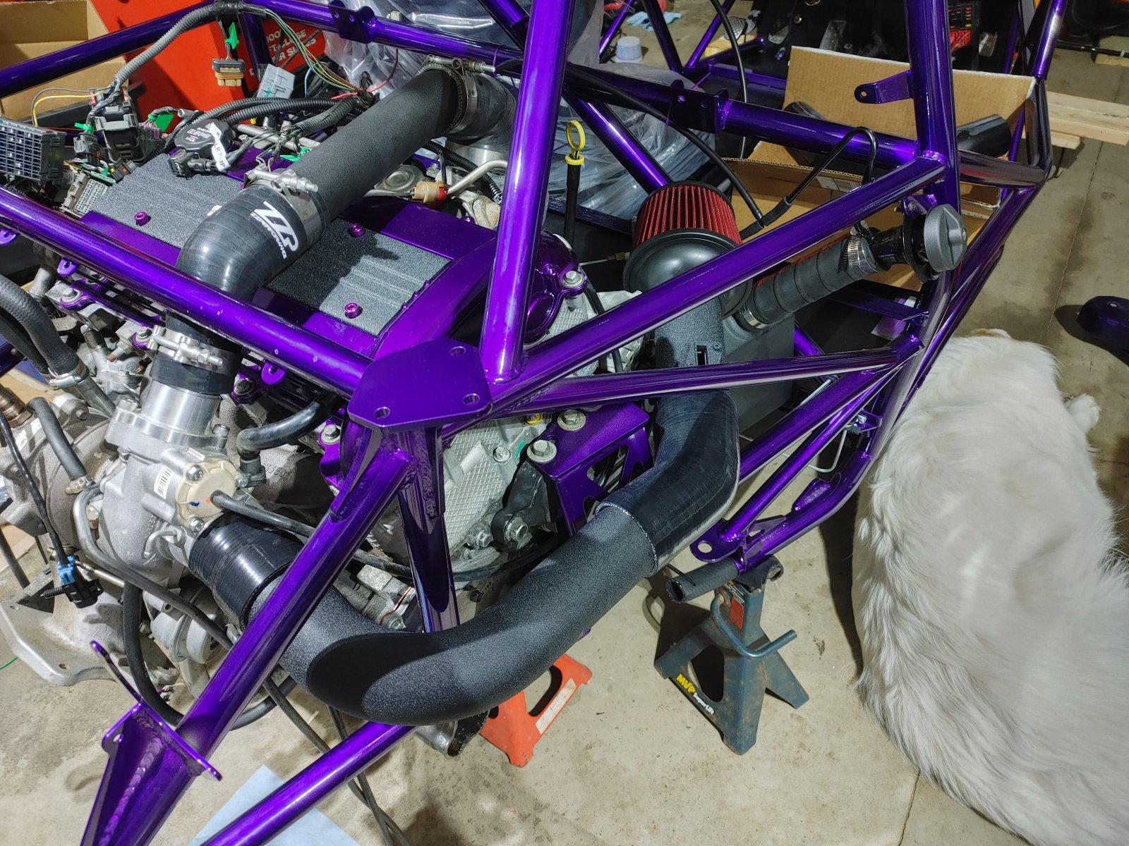
I only have a couple of connections I need to go back and identify in my pre-tear-down pics. My harness was pretty rough and I'm trying to tidy it up before rewrapping and installing it.
Desert Sasqwatch
Bigfoot Goblin
- Desert Sasqwatch Bigfoot Goblin
I had to look twice and remember you did the LSJ turbo conversion - no A2W intercooler on top of the engine.  Your build is looking great!
Your build is looking great!
Sluggonaut
Goblin Guru
- Sluggonaut Goblin Guru
I had to look twice and remember you did the LSJ turbo conversion - no A2W intercooler on top of the engine.
That's been the challenge so far - this is my only experience with the platform and the donor was already swapped when I bought it. I'm still figuring out what is stock vs aftermarket. I had to order another bracket for the Option B tank because I didn't know that was an option and I thought they all had 2 tanks. I'll just keep solving the puzzles until there are none left.
Similar threads


- Replies
- 2
- Views
- 663

- Replies
- 168
- Views
- 19K