• We've upgraded and reskinned the forum. Notice something off? Email us at [email protected] and we'll fix it.

V1 No crank, no Start, no Panel lights

Rttoys
 
T
Do some searching around here. ,any come up with something

Here is another direction that I want to ask about.......I am finding that folks don't know what I am referring to when I identify the X2 connector at the ECM. So before I ask about specific inputs or outputs, I have to ask what may be a silly ass question.....do you understand that the technical terms for the two major connections at the ECM are X1 and X2?
 
G
Yes
Here is another direction that I want to ask about.......I am finding that folks don't know what I am referring to when I identify the X2 connector at the ECM. So before I ask about specific inputs or outputs, I have to ask what may be a silly ass question.....do you understand that the technical terms for the two major connections at the ECM are X1 and X2?
yes, but without a wiring diagram to look at it doesn’t mean anything . No one has this stuff in memory to say what powers a certain pin or whatever. Most of the regulars on here are several years away from their build. And a lot don’t have the LNF.
 
G
Thanks for that......yes, the pink wires that I am observing are all ignition and supposed to be hot during run/start. Do you think maybe the anti theft is preventing them from getting 12v power?
Vats doesn’t kill most of the pink wires if any. This is why I keep asking about wiring diagrams. You can see where each one gets power.
 
T
Here is another direction that I want to ask about.......I am finding that folks don't know what I am referring to when I identify the X2 connector at the ECM. So before I ask about specific inputs or outputs, I have to ask what may be a silly ass question.....do you understand that the technical terms for the two major connections at the ECM are X1 and X2?

Do some searching around here. ,any come up with something


Here is another direction that I want to ask about.......I am finding that folks don't know what I am referring to when I identify the X2 connector at the ECM. So before I ask about specific inputs or outputs, I have to ask what may be a silly ass question.....do you understand that the technical terms for the two major connections at the ECM are X1 and X2?
I already have the 8000 page pdf manual. I have been studying it for a very long time. It is cumbersome but it is way better than the one you sent in the link.
 
Last edited:
Dale E
Most all of your pink wires will be switched through a fuse. Recheck fuses!
Is the small wire from Battery Positive connected to the BCM? There maybe a plug or inline fuse.
BCM -- check #8 IGN/SW/PK3+ (2amp) fuse. And #25 ECM/TCM (10a) fuse.
Engine fuse box:
Check (30a) crank fuse, crank relay and RUN/CRNK relay.
RUN/CRNK relay - IP IGN (20a) fuse.
BCM 2 (40a) fuse connects IGN/SW PK3+ fuse B (2a) connects IGN/SW
Connects BCM , theft and IGN/Lock solenoid

Are you pushing in the clutch when turning the key? Some folks before forgot to do that.

You're in Kerrville, TX, so about a 7 hour drive for me. There are Goblin owner/builders in Texas. I said in a DM if you were close I would come do a hands on with you. Have you reached out to anyone to do that? At this point I think that is your best way forward.

The folks on the forum are chasing ghost along with you. Your problem needs eyes and hands on diagnosis. Ask for help - please!
 
T
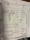
After several days of searching I finally found the wiring diagrams that I've been deperately searching for. The diagrams provide all the flow paths between the BCM and the ECM, which I am hoping will lead to some solutions in the coming days. The diagrams have answered my very first question and a few more. However, I have quickly hit a wall.....

My first priority is to start and run the engine with the ignition switch. The attached diagram shows the yellow wire which provides 12v ignition power to the 85 relay pin at the crank/run relay. With ignition on, both the 85 and 86 measure 13v. The 30 pin always shows 13v. However, the 87 pin and the ECM/Trans fuse does not get power with the ignition on.

This would normally indicate a faulty relay, however, I have tried 4 of them, including 2 that I tested. Both of the relays that I tested were good.

Thanks for all your assistance.
 

Attachments

Dale E
Try ground jumping the 87 pin?


1788476604053.png
 
duthehustle93
There's a 5V reference switch and it compares this to the 12V switch for redundant verification on ignition switch position. There's an explanation about how it works and why it exists near the end of the thread. I spent a lot of time suffering with our weird ignition system when trying to figure out how to wire in the kill circuit on my kill switch. It might be worth verifying both your 12V and 5V side are doing what they're supposed to.

 
T
There's a 5V reference switch and it compares this to the 12V switch for redundant verification on ignition switch position. There's an explanation about how it works and why it exists near the end of the thread. I spent a lot of time suffering with our weird ignition system when trying to figure out how to wire in the kill circuit on my kill switch. It might be worth verifying both your 12V and 5V side are doing what they're supposed to.

Thanks for that. Where you show 5v ref I show always B+ hot. Thanks for checking.
 

Attachments

G
If you are checking with the relay in place you are going to pass 12v through the coil relay from pin 85 and can measure voltage at pin 86 when checking with volt meter to ground. If the relay isn’t engaged, you don’t have a good enough ground to allow current to close the relay and you are missing good contact at what was ground G101.

If you had told me earlier that you couldn’t find the correct wiring diagram I would have taken the time to dig it out. I’ve got a lot going on in my life right now and haven’t been home much but would have dug through the service manual.
 

Attachments

  • image.jpg
    image.jpg
    597.1 KB · Views: 1
T
If you are checking with the relay in place you are going to pass 12v through the coil relay from pin 85 and can measure voltage at pin 86 when checking with volt meter to ground. If the relay isn’t engaged, you don’t have a good enough ground to allow current to close the relay and you are missing good contact at what was ground G101.

If you had told me earlier that you couldn’t find the correct wiring diagram I would have taken the time to dig it out. I’ve got a lot going on in my life right now and haven’t been home much but would have dug through the service manual.
Yes, I realize that now....guess my frustration has gotten the better of me.....and I've thought about how I should have been a little more direct. Sorry....I've ran lots of wires and never been quite this stumped
 
G
I don’t know where you checked voltage for pin 87, but the fuse box contains an internal circuit board that I think delivers voltage to the various fuses shown in my attachment. If the relay is closing when you turn the switch on, it’s possible the board is damaged. Check the other fuses and see if they have power if the relay is clicking.
 
G
The most likely cause of this is a bad ground on 86 g101 Pin x3-f2. When you say things like the relay is good and you checked it with an ohm meter, I have no idea what that means. Can you hear it click in the car when applying power? Is this a check with a loose relay?
 
T
The bench test for the relay..... when you put 12v to the 85, ground the 86 to the negative battery terminal....then check resistance between the 30 and the 87 and get 0.1 ohm....

I am getting 13v at 86 which indicates good ground.....not sure I see the point of going all the way to the connector.

On a roll...keep it going 09, SS, TC cousin!
 
G
No 12v at pin 86 does not indicate a good ground. If you are measuring with a voltmeter from a known power source to 86 as ground, you have to remember that a voltmeter meter doesn’t really allow current through, or only very small amounts, less than it takes to close the relay. So it might “see” ground but not be good enough to carry current. If you are measuring from 86 to a ground with the relay plugged in, then its passing voltage through the relay and might not see ground at all or again not actually enough ground to carry current.

Is the relay clicking? If you won’t answer this I quit.
 
Back
Top