Keckster
Well-Known Member
- Keckster Well-Known Member
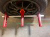
Not to highjack mid thread but if anyone is looking to assemble the 3d printed laser alignment system by diyfabshop I have modeled and used an adapter to mount to the goblin cage utilizing a worm gear clamp. Utilizing this system I was able to get the car the most stable it has ever felt! STL file posted below and in the 3d printing thread.


My most recent alignment stats are:
My most recent alignment stats are:
Front Left:
- Caster: -9.1°
- Camber: -0.8°
- Toe: 1mm in
Front Right:
- Caster: -9°
- Camber: -0.8°
- Toe: 1mm in
Total Front Toe: 2mm in
Front Axle Notes:
Tire Temperature normalized perfectly across the tread at 15psi during competition with chalk mark wearing perfectly.
Rear Left
- Camber: -1.9°
- Toe: 1mm in
Rear Right
- Camber: -1.9°
- Toe: 1mm in
Total Rear Toe: 2mm in
Rear Axle Notes:
Tire temperature was low on the inside shoulder but the chalk mark was showing full tread usage at 18psi
Disclaimer: I have modified my suspension this past winter moving pickup points, adding spacers to the wheel hubs, and raising the ride height to play with roll centers so my alignment settings may work for me and not a stock chassis.