Mikes Extended, Full Frame Goblin - 2009 Cobalt LS with 135k donor

Traé

Goblin Guru
The 1st picture is what I have saved for the button panel. 2nd pic is the list that is sent with the order, I pulled that from the link I mentioned above. The pink and green wires I have tied together are from the gauge cluster and feed the info & return. I have an 06 with a 4 spoke wheel (early model). The late model, seeing in your profiles “about” section states you have an 09, will only have a green wire as mentioned in the wiring harness videos.
 

Attachments

mike_sno

Goblin Guru
Well this picture 3678 explains the ACC, Accessory. Never saw that picture before. Funny thing is, my car had Fog left them in the harness for exact that purpose. Meas ACC switch is clear.

I have the Darkgreen/White cable ciruit 1358 going to the instrument cluster. From the Picture, this should be the Return signal.
But in the steering wheel schematics this circuit is not showing up.
I tried to pull that wire up to 12V and down to ground to see if the DIC changes, but nothing.

The pink cable with seems to be the info button seems to be missing. Now the issue is, I don't know where the pink cable is supposed to becoming from. The wiring diagram picture I posted earlier is the only place where I found the Info and Return switch and they are not labeled in a way that I can find where this cable should be coming from.
 

mike_sno

Goblin Guru
This mystery continues. According to this
44665


The DarkGreen/White goes to pin 2 of the Instrument cluster and is the Return button. Circuit 1358
The Pink Wire goes to pin 10 of the Instrument Cluster and is the MEnu Switch button. Circuit 893

However, my plug on the Instrument Cluster has this pin layout.

And here comes the DarkGreen/White wire Circuit 1358 on Pin 5, while the Pink wire is not existing at all.

Pins 2 and 10 are not wired up in my car. So the diagram picture I posted above seems to be wrong for my car. I will try to just ground Pin 2 and 10 of the IPC Plug and see if the DIC changes.
 

mike_sno

Goblin Guru
ACC is probably the "accelerate" button for cruise control. I gutted all of my cruise control stuff and didn't do any wiring for it.
Looks like you found the other two. "Info" cycles through the electronic display on the cluster. "Arrow" is enter. You hold it to reset your trip odo. These two follow the same path and use resistors to let the computer which button is pressed.
Aha!! Do you know the resistor amount??
 

Ross

Goblin Guru
Your donor has the late model wiring for the info/return buttons.
The picture above with the pink & dk green/white wires is the early model buttons.
Here is a picture of the late model wiring, with my comments on how to wire the early model ones over top of it.
Resistors are 715 ohm on the return button, and 1270 on the info button.
 

mike_sno

Goblin Guru
77.9mm pulley = 3.066" which looks just like Rttoys GM Stage 2 setup. Also, those blue anti-tamper bolts are used in this.
The injectors come back as GM Stage 2 injectors as well, they flow 42 pounds.

When measuring, I went with the top of the ribs (Peak) and not the bottom (Valley). When I did that I got the 71mm on the ZZP unit that arrived and it is marked as a 2.8" pulley. (71mm / 25.4 = 2.795" --> 2.8"). I would be willing to trust that the number you get that way is close to the 77.9 etched on the pulley face.

Since you have the rail and injectors out, change those insulators for fresh ones even if they look ok. They are super cheap and easy to swap now while it's all apart.
I simply created a quick drawing of the pulley I have. Is your pulley smaller?
So it seems I have the Stage 2 Pulley?
There is 100% no where on my pulley a 77.9mm measurement. Just the stamp upfront says 77.9.

44666
 

Robinjo

Goblin Guru
I simply created a quick drawing of the pulley I have. Is your pulley smaller?
So it seems I have the Stage 2 Pulley?
There is 100% no where on my pulley a 77.9mm measurement. Just the stamp upfront says 77.9.

View attachment 44666
It should be the 76 number, or at least that is how I measured mine. 76mm = 2.99" --> 3.0" pulley
 

Gtstorey

Goblin Guru
77.9mm is probably belt centerline.

We are only talking about something like 2% here. The difference in actual psi will be negligible.
 

mike_sno

Goblin Guru
77.9mm is probably belt centerline.

We are only talking about something like 2% here. The difference in actual psi will be negligible.
In that case the 71mm from @Robinjo should be 73mm = 2.87in.

It make sense that it's middle of the belt as that would allow propper rpm calculations.
 

mike_sno

Goblin Guru
..... You will also need to keep your base model thermostat housing instead of the LSJ thermostat housing and may need two coolant tees to tie the oil cooler in to the coolant line, there's details on that in my build thread that I can dig up if you need. If you're keeping the supercharger, your main cooling line to the frame (pass side) may need to be reworked anyway. That's just off the top of my head.
@Rauq I exchanged the thermostat housing like you said to make it work with the F23 gearbox. Since I am missing now the connections for the oil cooler, why did you decide to put tees and put the oil cooler in the main line instead of the hose which is in the picture below? I believe that was the small passenger room heat exchanger. Have not yet plumped the oil cooler and was wondering if I could do that.
44689
 
Last edited:

Rauq

Goblin Guru
The way I did it is basically the same as the factory LNF configuration. I don't remember if I really investigated using the heat exchanger lines. You'd have to dive into the circuit flow to make sure that you're getting a sufficient flow of appropriately cooled fluid through there for it to work. A lot of folks focus on the oil cooler getting the oil as cool as it can be, but it also helps bring oil temps up if the oil is cooler than the coolant.
 

mike_sno

Goblin Guru
So, I have something going on with my (rear) lamps. What is working:
- Reverse
- Brake incl 3rd
- Turn left and right
- Hazard
- Front lights seems to work as expected.
- Turn Signal front and back

What is not working:
Regular light

I would imagine that the regular light is either a lower voltage of the brake light or an extra wire.

I have 4 wires going to my rear lights:
Brown = Seems to be ground
Green = Reverse. Has 12V towards Brown and ground when I put the gearbox in reverse.
Yellow = Brake/Turn. Has 12V towards Brown and ground when Hazard, Turn or Brake.

Black = ?? This seems to be the normal light.

If I switch just the lights on, then I measure nothing on the Black cable, but for whatever reason I meausre 3.8V on the brown ground wire.
I first thought it's a bad ground and jumped another ground cable on the brown one. As soon as I pull the brown one to ground the front lights going from lo to hi beam.

I am looking at the diagram and can not find what could be wrong.
 

Ross

Goblin Guru
Have you checked the fuses already?
...
I have 4 wires going to my rear lights:
Brown = Seems to be ground
Green = Reverse. Has 12V towards Brown and ground when I put the gearbox in reverse.
Yellow = Brake/Turn. Has 12V towards Brown and ground when Hazard, Turn or Brake.

Black = ?? This seems to be the normal light.
...
So these wire colors are the Chevy wires going to the rear lights?
If so, the black is ground.
brown is running lights
green is reverse
light green is right turn signal/right brake light
yellow is left turn signal/left brake light
 

mike_sno

Goblin Guru
Well, this is all very weird. Spend the complete day to figure out what is going on.

First of all: I had to find out the real wiring of my tail and head lamps. Unfortunately I have no diagram of those and could not find one online. Anyway, figured that out.

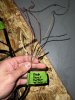
Then like Ross said, Black is Ground and Brown is Running light. Yellow is the Turn light.

However, before I even came to this point, I switched the car on this morning and the tail lights were illuminated right away. First I thought, the stop switch must be bad. Disconnected the stop switch, but no change. Then I found out that on the top side of the switch I have 12V as supposed to and on the bottom side around 8V coming from somewhere. I checked the connection back to the BCM C2 54 was also getting the 8V and that seems to be enough to switch on the tail lights. Hmm, then I looked for the C201 plug which I could not find until I remembered that this was one of the plugs which were cut of of the harness.
Then I disconnected the C3 Plug of the FBU. And the 8V were gone. For the moment... Aha, so something from the FBU was feeding voltage back to the system. Tried to figure out where it came from and ended up cutting the wires to C3 F3 and F4 one by one.
I have now identified the cable which comes from the 3rd brake light and the cable which comes from the Stop lamp switch, I also found the wire which goes to the Engine Control Module. Now the tail light works as expected. Running, Turn, Stop and Reverse. The 3rd currently can't work due to the cable being cut. However, all the sudden my front lights stop working at all and it seems like I forgot to pull the ground wire. I have 3 wires high, low and park. No ground. I pulled temporarily a ground to the front lights and now they are working again. My front lights don't have a parking lamp so this cable is not used in my goblin, but the wire has voltage when park lamps are on. To be sure I pulled the high and low beam fuses and confirmed that the front lights are connected correctly.

Well the story continues. All the functions, park, turn, brake, hi and low beam are working. But when the car is off the park wire has 8V again.... Furthermore when I turn on the turn signal, the little park LED in the turn signal goes off when the turn signal goes on. They are blinking opposite. Well, I thought maybe not a good ground at the turn signal and pulled another temp ground, but no change.

For some odd reason the Park fuse now has 8V on both sides. I wonder if the Park Relay on the PCB board is damaged. The manual says it's not serviceable, but I don't believe that :D Has someone done that? Or any better idea where this 8v could come from? If I pull the park fuse, the park lights in the mirrow and front are not working as expected. But also the running lights on the rear lights are not working. I wonder if I should just pull another cable and put the rear running lamps parallel to the front lights.

Anyone any good ideas what to check now?

I first thought the problem with the 8V came from here, but now I find out that the 8V seems to come from the park light.
44697
 

Ross

Goblin Guru
Since pulling C3 fixed the 8V issue, I started there. On my 06 LSJ, The C3 is mostly lights.
So I would start by pulling the lighting fuses one at a time, and see if that one of them is introducing the 8V.
My 06 LSJ has 4 10A fuses for the headlights, a 15A for the parking lights, 10A for the backup light & 15A for the fog lamps.
If it isn't one of those fuses, keep pulling fuses and testing... find out which fuse stops the stray 8V.
44704
 

mike_sno

Goblin Guru
Yes, I pretty much pulled the fuses. Did that also to verify that everything is working as supposed to.

I think there is something going on with the Park Circuit. If I pull that fuse and measure at the connectors of the fuse, the side which points to the center of the car has 12V the other side nothing and no 8V on any other point. If I put the fuse back in I measure on both sides of the fuse 8V. For me that sounds like the PCB relay is not interrupting the circuit correctly. As long as I just measure I get 12V but as soon as I have load on the circuit it collapses to 8V. But if I leave the Park fuse out the rear running lights don‘t work anymore.
 

Ross

Goblin Guru
Try soldering on a new parking lamps relay? It is the only thing between the 12V power and the parking lamp 15A fuse.
Guess you should test it first. Measure resistance between the 12V post on the FBU, and the 12V side of the parking lamp fuse. Should be under 1 ohm... but if the relay contact is worn out, it will be > 1 ohm.
I see the parking lamp 15A fuse in the fuse box underhood, but I don't see a removable relay for it, so I am guessing it is soldered onto the PCB board.
44705
 
Last edited:

mike_sno

Goblin Guru
Yes, I wonder where this PCB board is. Maybe I swap the complete fuse box with the LAP fuse box I have laying around. Have to check if they are interchangeable.

Before I do that, I just thought about something else. I will try to pull the park fuse again and on the 12V side I will introduce some load and see if the voltage collapses again. Then test load when the relay is on and see what it does.
Has anyone seen the PCB board? I couldn‘t find anything on google.
 
Top