Ross's extended city, easy entry Goblin- 06 SS/SC, NW Arkansas
- Thread starter Ross
- Start date
Ross
Goblin Guru
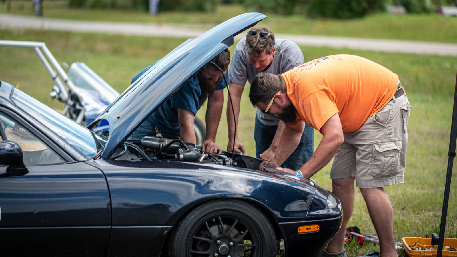
So I am talking to another driver at yesterday's autocross,
and some guy in an orange shirt, walks up to us, grabs my tool box, and rolls it away.
I stand there kind of stunned, thinking he could at least ask me... but he is in a hurry, and doesn't even seem to notice me.
I walk over to his car, where he is searching thru my tools, for just the right socket and ratchet.
"So what you guys working on?"
"Power steering - it threw the belt off."
"Oh, I heard the announcement that someone was looking for their power steering belt. You found it?"
"Yes, someone found it for us. I need a wrench."
"Those wrenches you grabbed are standards, these ones are metric."
So they proceed to remove enough parts to get to the belt,
and I help them with grabbing the right tools.
After 10 minutes they are wrapping up the install, and I ask them
"Are these Jason's tools?"
"Yes, he said we can use his."
"Well Jason's tools are over there in the red tool chest. These are my tools."
"Oh my goodness! I am so sorry... I didn't mean to grab your tools..."
I am laughing too hard...
"No worries, you seemed to know what you're doing, I didn't want to get in the way. Thought I could give you a hand."
Quite a few of us enjoyed the story, including Jason and I.
Jason pointed out to me that he is an expert in Ecotec timing chains, and he is going to hook me up with some new timing chains and sprockets!
Last edited:
")
Ross
Goblin Guru
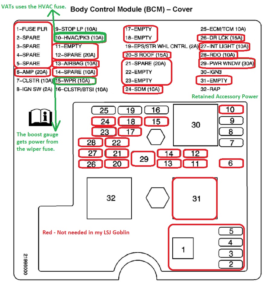
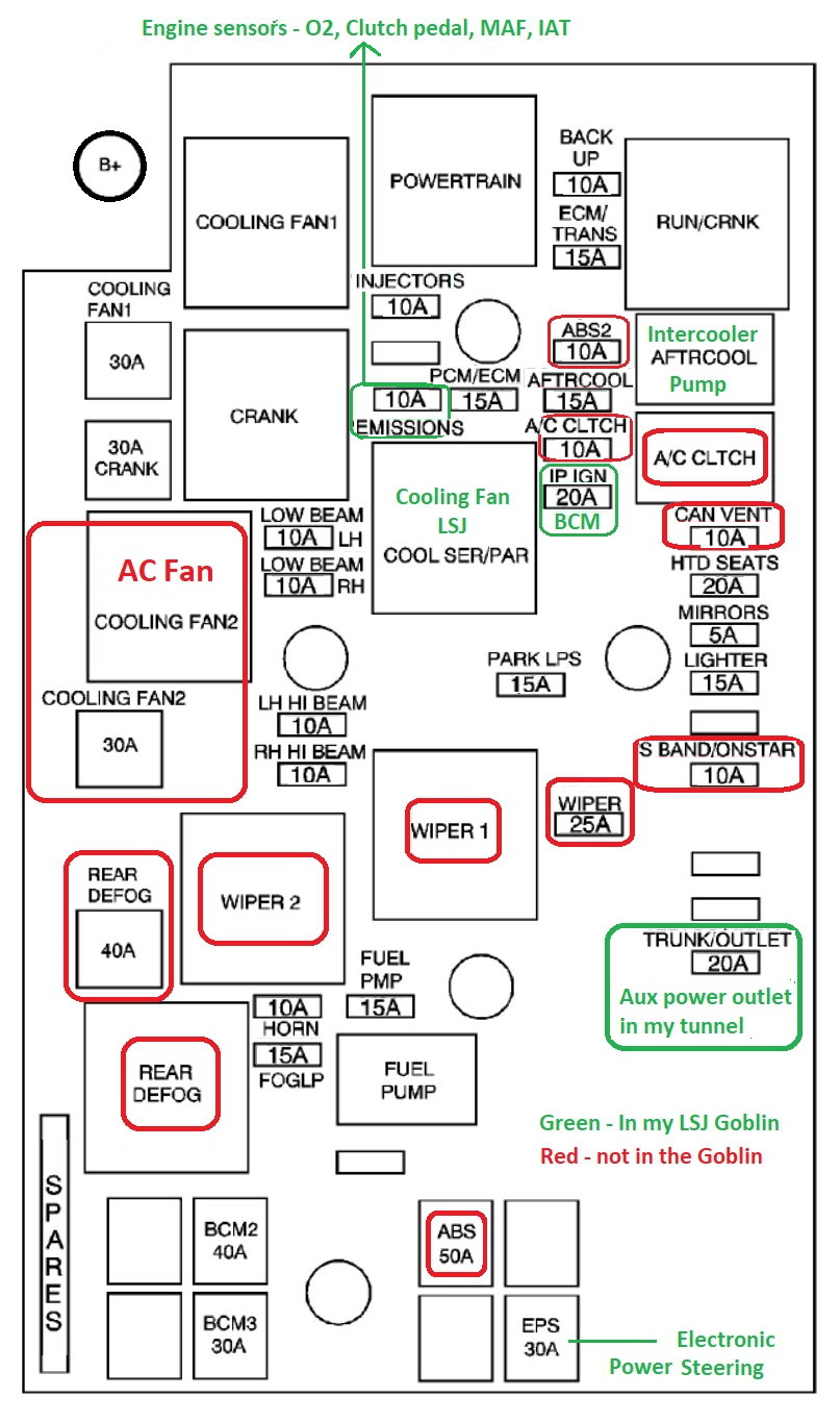
I decided to document the fuse boxes, and identify what isn't needed in my LSJ Goblin.
I reoriented this fuse map to the direction it is mounted in the Goblin.
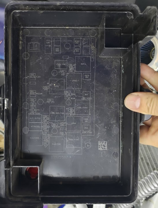
The engine fuse box lid is low contrast, making it hard to read.
This copy is much better. Time to print it, and put it in the fuse box lid.
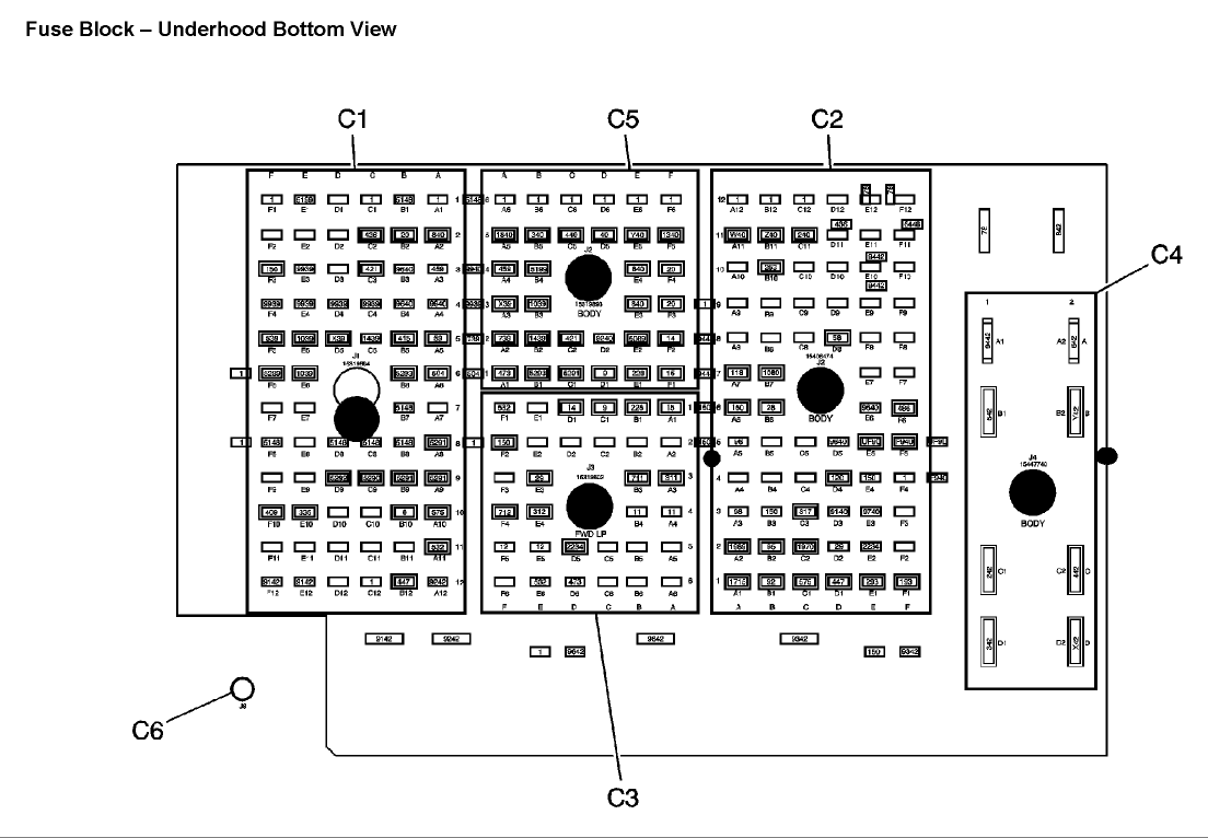
Here are the internal wiring diagrams of the 2006 2.0L SS SC fusebox. These are hard to find on AllDataDIY, and barely readable little numbers.
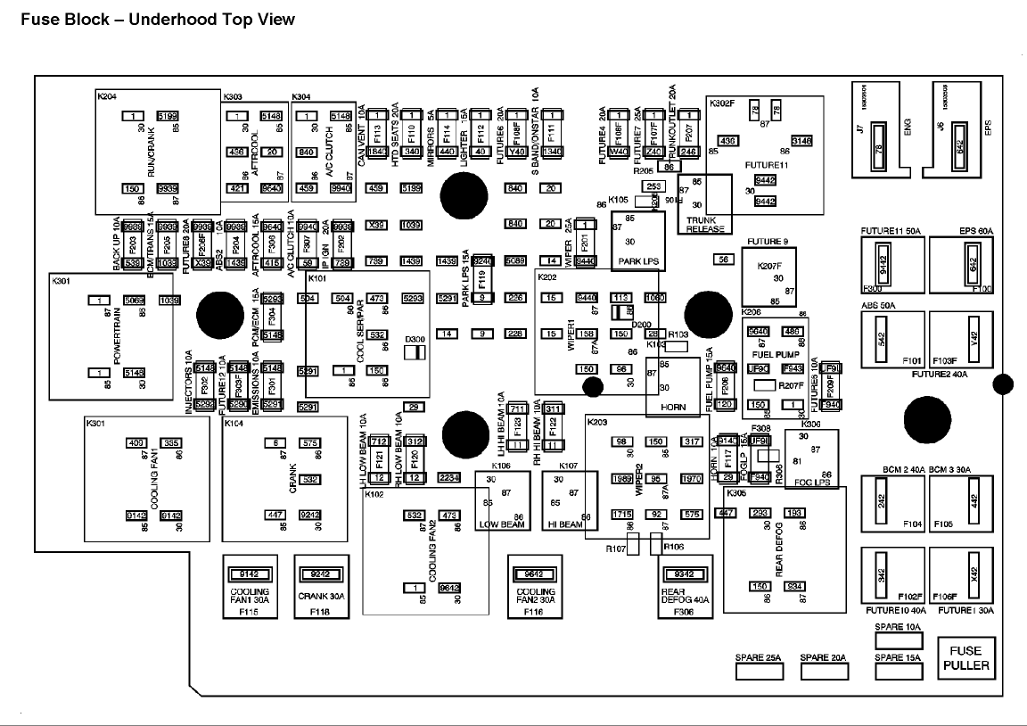
I reoriented this fuse map to the direction it is mounted in the Goblin.
The engine fuse box lid is low contrast, making it hard to read.
This copy is much better. Time to print it, and put it in the fuse box lid.
Here are the internal wiring diagrams of the 2006 2.0L SS SC fusebox. These are hard to find on AllDataDIY, and barely readable little numbers.
Last edited:
escapepilot
Goblin Guru
Thanks for posting that, Ross. It should come in handy in a few weeks.
Ross
Goblin Guru
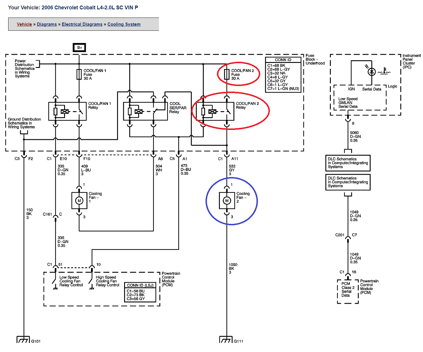
The engine fuse box has a relay labeled COOL SER/PAR that I didn't know the purpose of.
I did a little research, and found out that it is used on an LSJ engine to run the FAN1 & FAN2 in series at 6V each.
In a Cobalt it will use the coolant temperature to turn on Fan1, and the AC Pressure sensor to turn on both Fan2 and the SER/PAR relay.
COOL SER/PAR is running 2 fans in SERial or PARallel. Since we have removed FAN2 and the AC Pressure sensor from our Goblins, we have disabled the low speed feature. In the goblin. FAN1 will come on high setting (full 12V) based upon the coolant temperature and PCM settings.
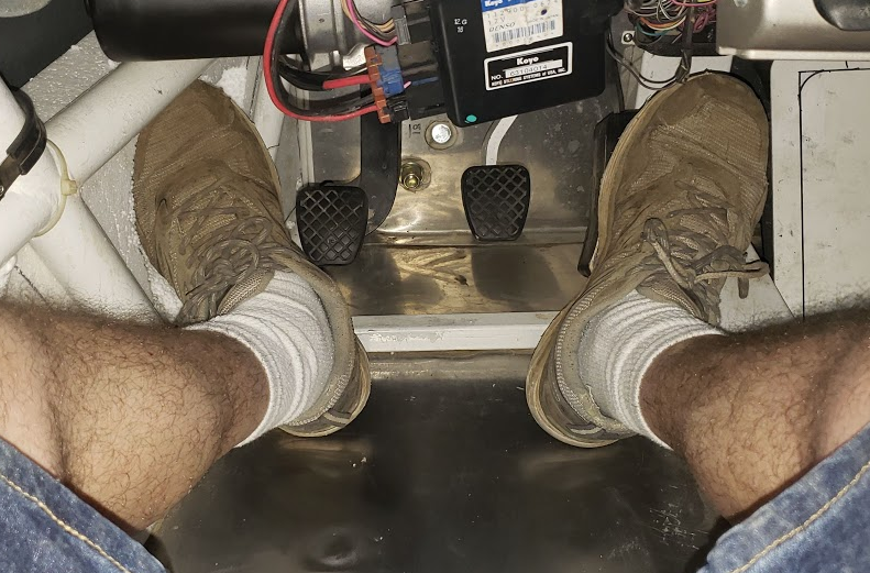
Today I furred out the side panel using 2" thick piece of foam, then carved a foot rest in the side.
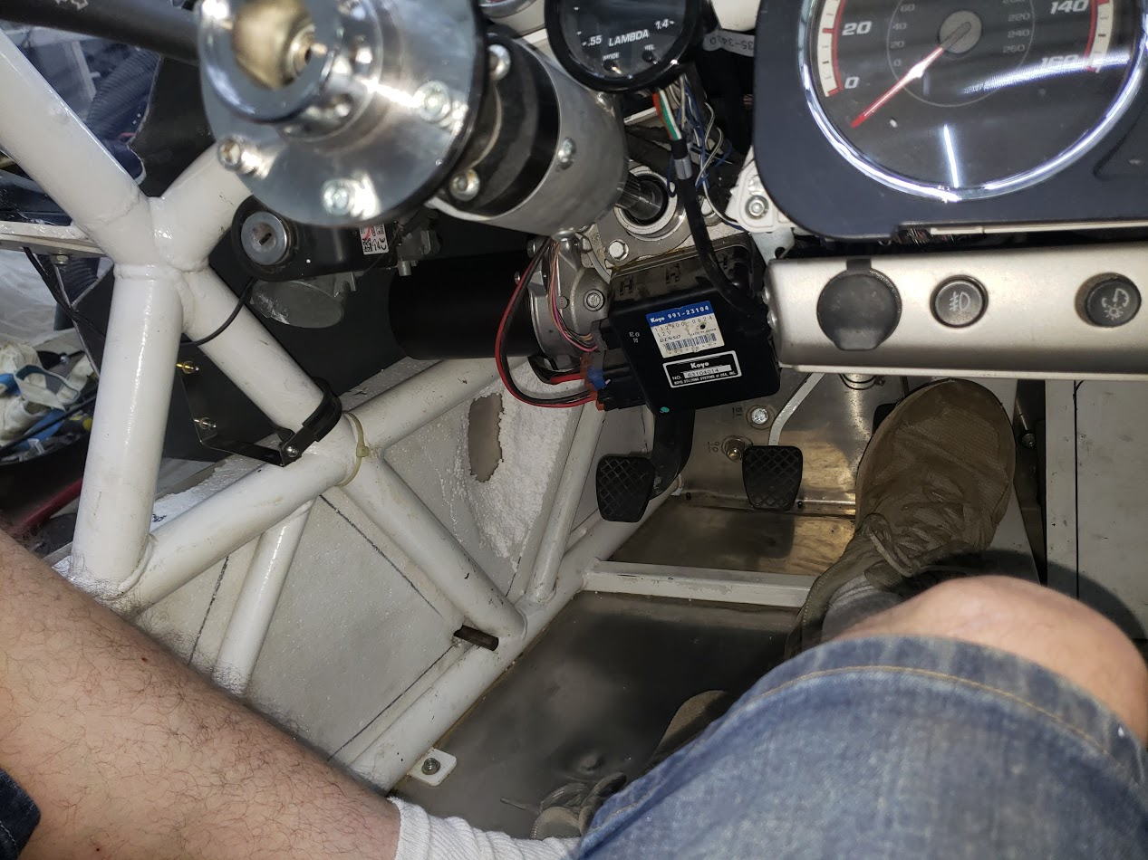
It helps reduce that gap between the panels
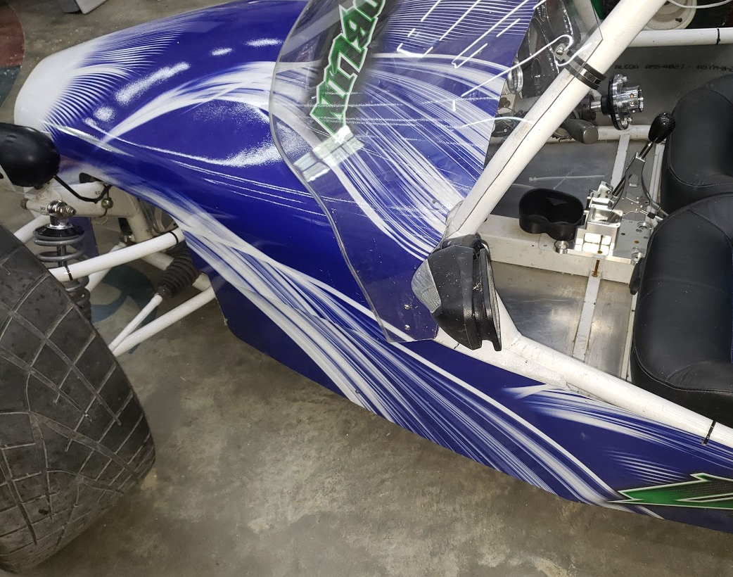
Ah, I finally got back my foot rest! Now I can have side panels and a foot rest.
I did a little research, and found out that it is used on an LSJ engine to run the FAN1 & FAN2 in series at 6V each.
In a Cobalt it will use the coolant temperature to turn on Fan1, and the AC Pressure sensor to turn on both Fan2 and the SER/PAR relay.
COOL SER/PAR is running 2 fans in SERial or PARallel. Since we have removed FAN2 and the AC Pressure sensor from our Goblins, we have disabled the low speed feature. In the goblin. FAN1 will come on high setting (full 12V) based upon the coolant temperature and PCM settings.
Today I furred out the side panel using 2" thick piece of foam, then carved a foot rest in the side.
It helps reduce that gap between the panels
Ah, I finally got back my foot rest! Now I can have side panels and a foot rest.
Last edited:
ctuinstra
Goblin Guru
I want to add a hitch for no other reason than this.
baustin
Well-Known Member
I also tried removing the wiper fuse from the BCM (http://dfkitcar.com/forum/index.php?threads/baustins-extended-track-06-ss-sc-donor-157-registered.1153/post-31687) but found out it killed my boost gauge. I have an 06 SS/SC LSJ, is your gauge still working after pulling the fuses?I decided to document the fuse boxes, and identify what isn't needed in my LSJ Goblin.
I reoriented this fuse map to the direction it is mounted in the Goblin.
View attachment 24704
The engine fuse box lid is low contrast, making it hard to read.
View attachment 24707
This copy is much better. Time to print it, and put it in the fuse box lid.
View attachment 24705
Ross
Goblin Guru
The goblin fan could be wired to run at 3 settings: off, low speed, or high speed. Right now the goblin uses off and high speed.
This would use the AC Pressure 5V sensor which controls the Fan 2 relay and the SER/PAR relay in a Cobalt. (This circuit could be used for other things that might be more important. For example: an oil pressure sensor and an alarm buzzer instead of Fan 2. This circuit value is available on the canbus, so it can be logged by HP Tuners or programmed to show on a canbus gauge.)
You could substitute a resistor for instead of Fan 2, and remove the Cool Fan 2 fuse & relay (so the resistor doesn't turn on without the fan on).
Then add a temperature 0-5V sensor to the engine coolant or engine oil, and wire it to the old cobalt AC Pressure sensor.
Then my radiator fan 1 would be able to run a low speed or full speed, depending on what the PCM wants. I can use HP Tuners to set the tables in the PCM to turn on the fan at full speed.
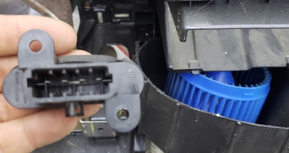
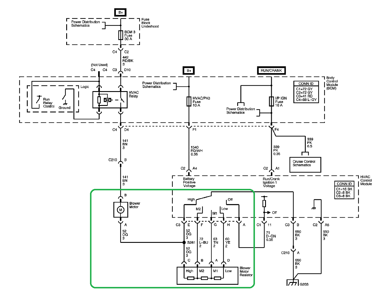
The resistor from the interior fan speed control could be repurposed in place of Cooling Fan 2.
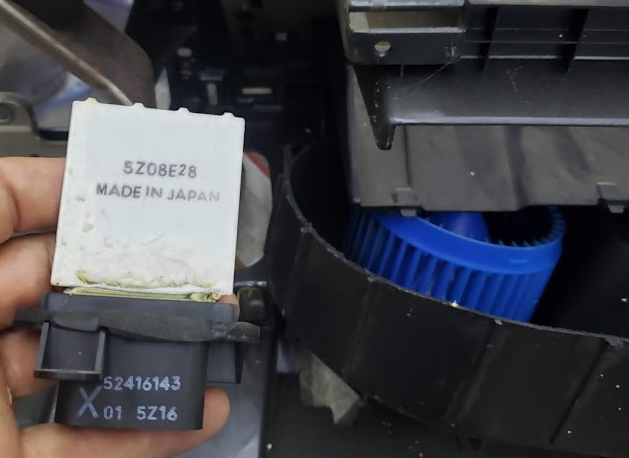
That speed control resistor normally runs in the moving air, to keep it cool.
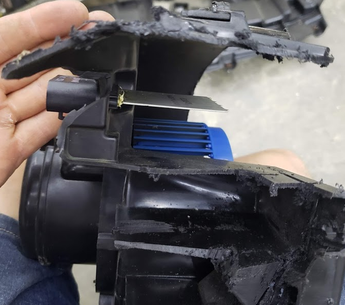
So mounting it behind the radiator fan should be good. Use the wires from Fan2, and route them to this speed resistor pack.
There are multiple speeds available to the interior fan, so you can pick what speed you want. I think I would use light blue wire (med-high speed) or the tan wire (medium speed). I would have to test the radiator fan, and see how fast it runs, and how hot the resistor gets. Only run the lowest speed (yellow wire) if it doesn't overheat the resistor.
This would use the AC Pressure 5V sensor which controls the Fan 2 relay and the SER/PAR relay in a Cobalt. (This circuit could be used for other things that might be more important. For example: an oil pressure sensor and an alarm buzzer instead of Fan 2. This circuit value is available on the canbus, so it can be logged by HP Tuners or programmed to show on a canbus gauge.)
You could substitute a resistor for instead of Fan 2, and remove the Cool Fan 2 fuse & relay (so the resistor doesn't turn on without the fan on).
Then add a temperature 0-5V sensor to the engine coolant or engine oil, and wire it to the old cobalt AC Pressure sensor.
Then my radiator fan 1 would be able to run a low speed or full speed, depending on what the PCM wants. I can use HP Tuners to set the tables in the PCM to turn on the fan at full speed.
The resistor from the interior fan speed control could be repurposed in place of Cooling Fan 2.
That speed control resistor normally runs in the moving air, to keep it cool.
So mounting it behind the radiator fan should be good. Use the wires from Fan2, and route them to this speed resistor pack.
There are multiple speeds available to the interior fan, so you can pick what speed you want. I think I would use light blue wire (med-high speed) or the tan wire (medium speed). I would have to test the radiator fan, and see how fast it runs, and how hot the resistor gets. Only run the lowest speed (yellow wire) if it doesn't overheat the resistor.
Last edited:
Ross
Goblin Guru
Come on by, and we can weld one in for you.I want to add a hitch for no other reason than this.
Good to know. I updated my BCM fuse diagram. I haven't tried pulling the wiper fuse, but I trust your research. Where did you get that nice electrical diagram from? I wish AllDataDIY was that nice.I also tried removing the wiper fuse from the BCM (http://dfkitcar.com/forum/index.php?threads/baustins-extended-track-06-ss-sc-donor-157-registered.1153/post-31687) but found out it killed my boost gauge. I have an 06 SS/SC LSJ, is your gauge still working after pulling the fuses?
Where did you get the tow hitch from? I tried to find just the hitch neck to slide into the subframe, but couldn’t find any except the 1” to 2” adaptersCome on by, and we can weld one in for you.
ctuinstra
Goblin Guru
That's assuming the resistor is about the same resistance of the cooling fan motor. If the cooling fan motor is a higher power fan (lower resistance and higher current) than the resistor, you would end up dropping most of the 12V along the resistor and little across the fan. That could quickly overwhelm the resistor and burn it up. A quick measurement of the resistor value and the motor might give insight of what to expect. It's going to take one heck of a resistor to eat up 6V at, says, 10A motor draw (60W resistor, that's a lot of heat).So if I removed the Cool Fan 2 fuse and relay, and substitute a resistor for Fan 2, then my radiator fan 1 would be able to run a low speed or full speed, depending on what the PCM wants.
The resistor from the interior fan speed control could be repurposed in place of Cooling Fan 2.
That speed control resistor normally runs in the moving air, to keep it cool.
So mounting it behind the radiator fan should be good. Use the wires from Fan2, and route them to this speed resistor pack.
There are multiple speeds available to the interior fan, so you can pick what speed you want. I think I would use yellow (slowest speed) or maybe the tan wire (medium 1 speed)... would have to test the radiator fan, and see how fast it runs.
Ross
Goblin Guru
That resistor is already is series with a 30A fuse, and the interior fan motor.That's assuming the resistor is about the same resistance of the cooling fan motor. If the cooling fan motor is a higher power fan (lower resistance and higher current) than the resistor, you would end up dropping most of the 12V along the resistor and little across the fan. That could quickly overwhelm the resistor and burn it up. A quick measurement of the resistor value and the motor might give insight of what to expect. It's going to take one heck of a resistor to eat up 6V at, says, 10A motor draw (60W resistor, that's a lot of heat).
The Cool Fan 1 is also on a 30A fuse. So actual fan motor amperage will come in to play here.
You are right, it might be an issue, but that resistor should be close. Not having enough air moving by it might also come into play here.
Since the resistor pack has different speeds to choose from, you could always use a higher speed, and see how hot it gets. Then choose a lower speed if it isn't overheating. I updated my previous post, mentioning that heat could be an issue.
Last edited:
baustin
Well-Known Member
I wish I could remember, I know I stumbled on it and looked to match exactly or at least for the wiper fuse wiring. It's been a while but I figure it came from one of the Cobalt forums. I thought it might've come from the Auto Zone free diagrams (similar to alldataDIY) but this is what I see from Auto Zone's page:Come on by, and we can weld one in for you.
Good to know. I updated my BCM fuse diagram. I haven't tried pulling the wiper fuse, but I trust your research. Where did you get that nice electrical diagram from? I wish AllDataDIY was that nice.
When I tried to find the same sheet from AllDataDIY, it makes it harder to catch the fuse feeding the boost gauge:
Not sure why the AllDataDIY doesn't show the same LSJ specific connection where I circled in red for both versions.
pisco
Well-Known Member
Ross is that beaver?