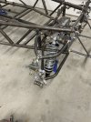
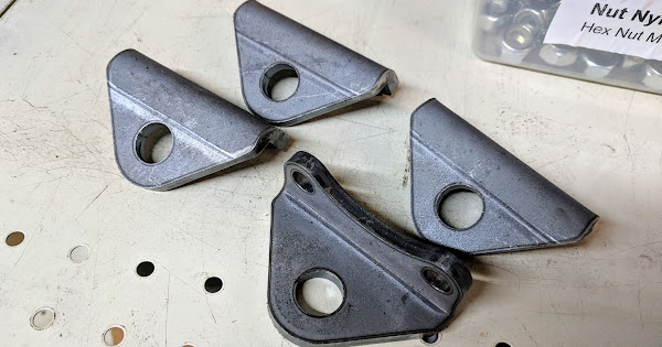
You're close. The lower rod end mount (curved/bend piece) needs to go on the inboard side of the upright. The steering arms do have a left/right, determined by the taper for the tie rod end which goes below the steering arm.
Folks have gone back and forth on the mounting holes for the steering arm, which ostensibly accommodates for different caster settings. For the average caster setting (8.5° ±1°), the conclusion I observed was that you want the tie rod end to be as low as possible, which means using the diagonal holes - front high, rear low. This is the way I set mine up most recently, and it seems to have less variation in toe across suspension travel than before, using both bottom holes. Presumably, with other steering arm mounting holes, there would be a much bigger change in toe across suspension travel (aka bump steer?). I also didn't have the energy to put a laser on the upright and watch its left/right displacement through suspension travel, which would've been far more conclusive.