
-
We've upgraded and reskinned the forum. Notice something off? Email us at [email protected] and we'll fix it.
You are using an out of date browser. It may not display this or other websites correctly.
You should upgrade or use an alternative browser.
You should upgrade or use an alternative browser.
V1 Fenix's Goblin #461 - 2010 Base Auto


Scott #321
Well-Known Member
- Scott #321 Well-Known Member
Haven't seen the dry ice blasting, I used baking soda. Did a great job but when I tore the engine down the following year I did find soda pockets under the intake around the injector insulation.

Fenix Nexen
Well-Known Member

- Fenix Nexen Well-Known Member
pulled out the gas tank, donor shell is done aside from parking brake...
ran brake line, was awful having to drill into the frame... the screws kept walking... one side didnt screw in all the way but its in sort of and stripped
painted part of the steering rack and the pedal housing... flipped the frame.. wiring harness kit will arrive tues...
garage is a mess, will have to dedicate a day or two to cleaning up...
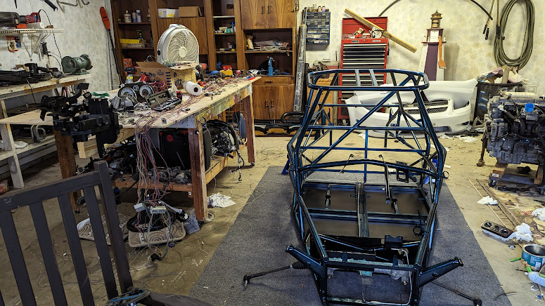
ran brake line, was awful having to drill into the frame... the screws kept walking... one side didnt screw in all the way but its in sort of and stripped
painted part of the steering rack and the pedal housing... flipped the frame.. wiring harness kit will arrive tues...
garage is a mess, will have to dedicate a day or two to cleaning up...

Metal Mech
Well-Known Member

- Metal Mech Well-Known Member
Garage is in better shape than mine. Or maybe just bigger which helps hahapulled out the gas tank, donor shell is done aside from parking brake...
ran brake line, was awful having to drill into the frame... the screws kept walking... one side didnt screw in all the way but its in sort of and stripped
painted part of the steering rack and the pedal housing... flipped the frame.. wiring harness kit will arrive tues...
garage is a mess, will have to dedicate a day or two to cleaning up...
View attachment 40232
Fenix Nexen
Well-Known Member
- Fenix Nexen Well-Known Member
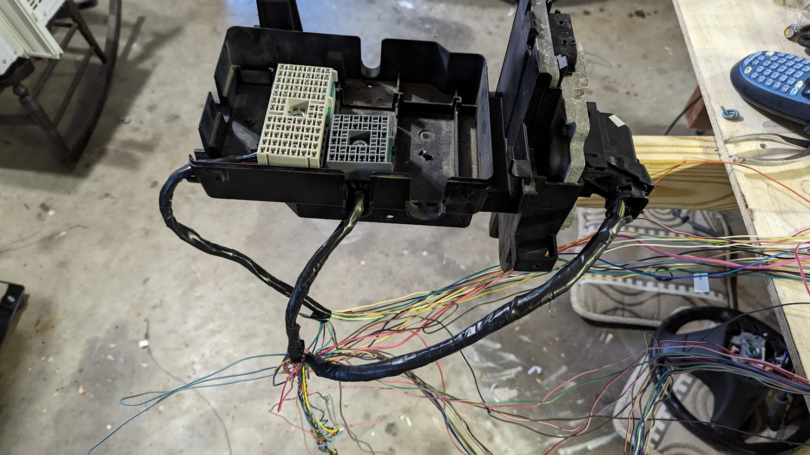
frustration as things with the harness do not match the new videos
what i see
what the guide sees
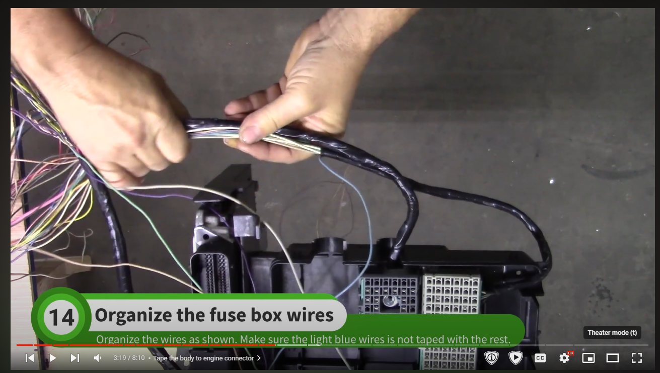
off the scour the old videos i guess
edit: old video point of view
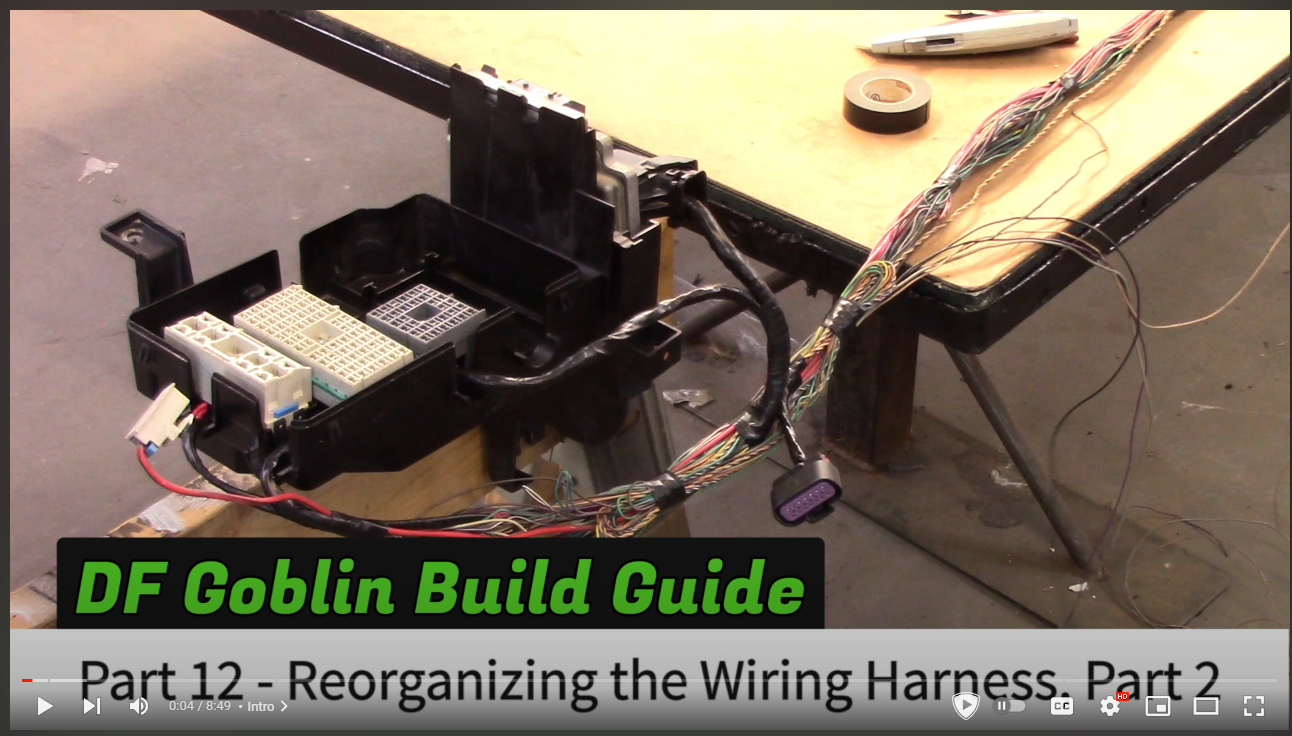
what i see
what the guide sees
off the scour the old videos i guess
edit: old video point of view
Fenix Nexen
Well-Known Member
- Fenix Nexen Well-Known Member
decided to move on and made it to labeling the body connector, seems the data wires at c5 and c6 was cut? did i make a mistake
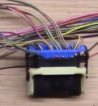
guess not but context would be nice
guess not but context would be nice
Last edited:
Fenix Nexen
Well-Known Member
- Fenix Nexen Well-Known Member
these data wires was cut at some point
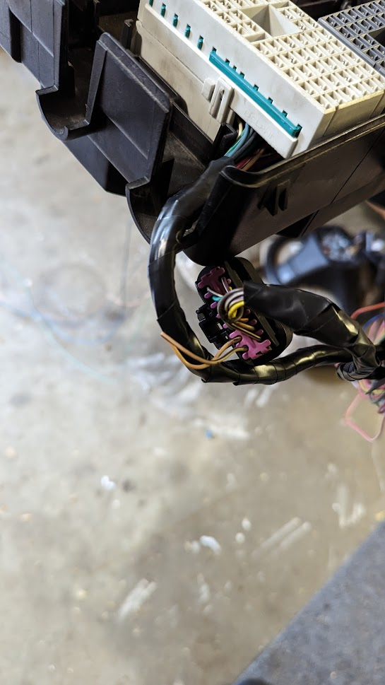
according to the older videos that should of not happened but in the newer videos i either made a mistake or was instructed to cut this?
i grabbed cut data wire i saved and soldered them back on, i dont know where this will lead?
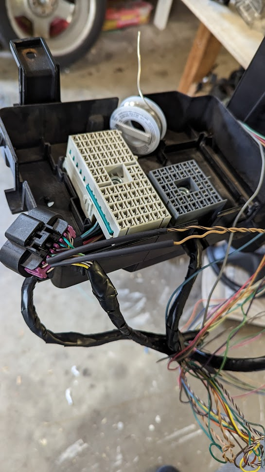
as mentioned earlier the data wires here was cut and completely thinned out
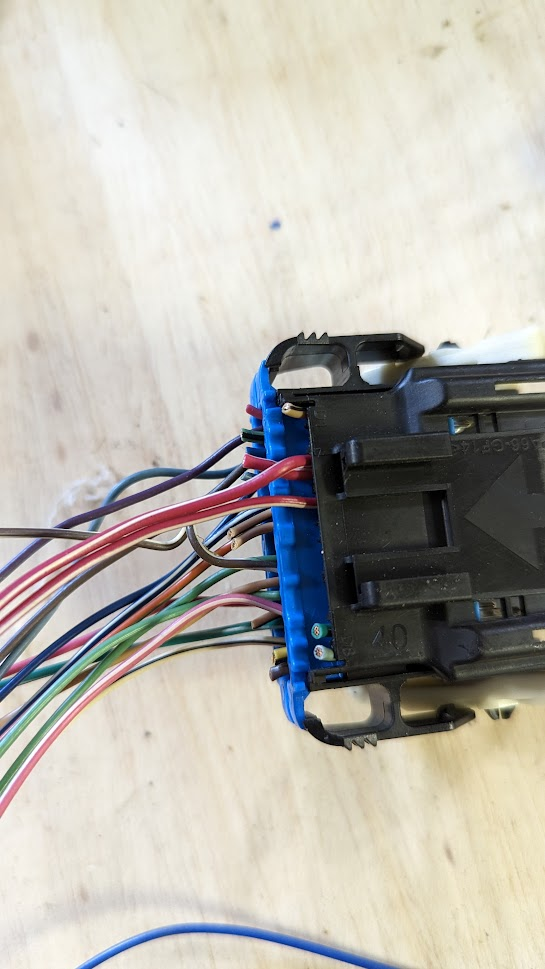
and i have an unused label for it
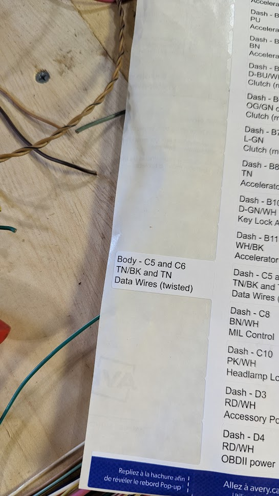
does the wire i fixed go to C5 and C6?
also the 6 inches of data wires sticking out here in the video are not there for me
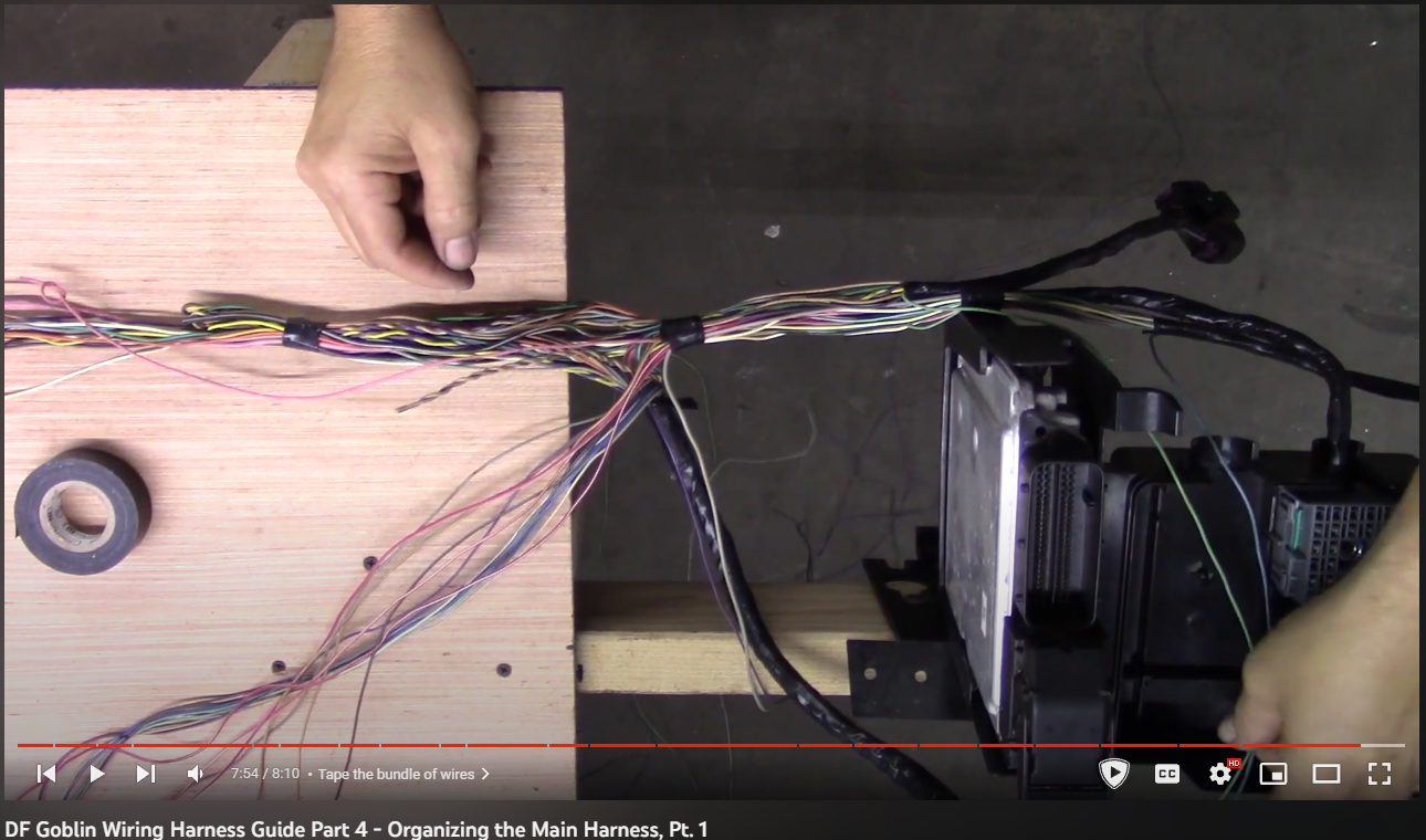
as mentioned elsewhere in the forum
and the data wire from the ECBM that i was told to keep connected to the ECM was either cut out or never existed
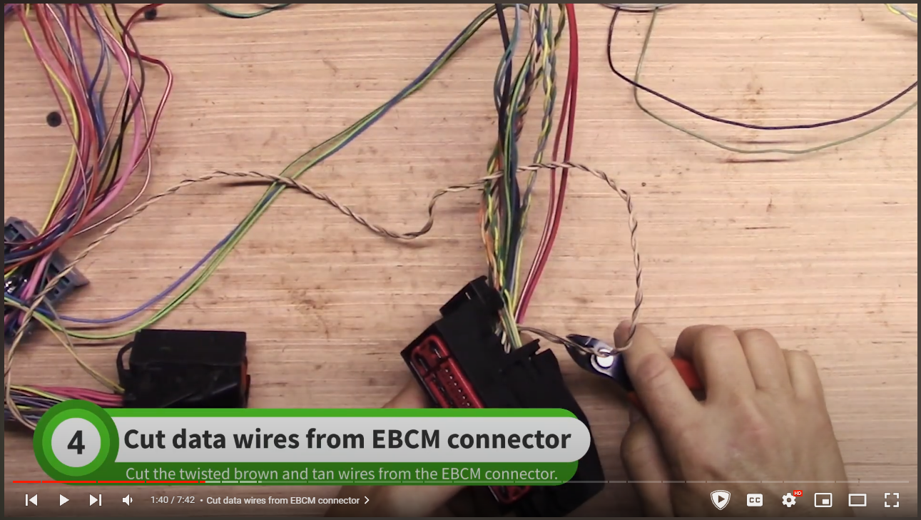
my EBCM was also black not red
some clarification and help would be nice
same issue here, reading has helped a little

 dfkitcar.com
according to the older videos that should of not happened but in the newer videos i either made a mistake or was instructed to cut this?
i grabbed cut data wire i saved and soldered them back on, i dont know where this will lead?
as mentioned earlier the data wires here was cut and completely thinned out
and i have an unused label for it
does the wire i fixed go to C5 and C6?
also the 6 inches of data wires sticking out here in the video are not there for me
as mentioned elsewhere in the forum
You can keep it for now. Later on in the combining videos you will tag and cut out the body connector and splice those body wires to the dash wires to the ECM. The twisted pair is the network cable running between all the computers in the system. If it does not make the complete path, the car will not run.
and the data wire from the ECBM that i was told to keep connected to the ECM was either cut out or never existed
my EBCM was also black not red
some clarification and help would be nice
same issue here, reading has helped a little
High speed GMLAn
on my X101 Body Harness to Engine Harness, I cut out the high speed GMLAN serial data wires during the main harness thinning videos. Is this correct or do we need them? It is the purple 14 pin connector.
Last edited:

Joebob
Goblin Guru

- Joebob Goblin Guru
I think you are ok with the thinning but I would leave a couple of inches in case of mistakes from now on and trim up at the end if everything is working. The labels are used to thin out the Body to dash harnes to have only one set of wires. This is the X201 connector that is removed from the system. You need to take the twisted pair from the BCM connector at locations 2 and 20 and make a path to extend them to the Body to Engine connector (X101) shown in the picture below to points B and A.
Then the twisted pair leaves the other side of the connector to the TCM plug pins 6 and 7. You can use a multimeter to confirm continuity of these wires. Correct any mistakes.
From the TCM, the twisted pair leaves out of pins 37 and 38 and goes back to the Body to engine plug at pins J and H can you can check continuity at those as well.
Lastly you can check that you have continuity to the other side of the X101 plug to the ECM pins at 44 and 43.
Note and WARNING: make sure you probe the pin recepticals in the TCM, BCM, ECU plus with a very thin wire or paperclip. if you stretch out the hole, it will lose contact with the computers and lose communication of the system and put e car in limp mode. Not fun to repin a connector.
Good luck and I hope that helps.
Joe
Fenix Nexen
Well-Known Member
- Fenix Nexen Well-Known Member
I grabbed a multimeter and did some learning and testing thanks to your help and I understand it now and managed to test cont by dragging the engine over and probing the tcm plug and the other end of the x101 connector. Thanks a lotView attachment 40315
I think you are ok with the thinning but I would leave a couple of inches in case of mistakes from now on and trim up at the end if everything is working. The labels are used to thin out the Body to dash harnes to have only one set of wires. This is the X201 connector that is removed from the system. You need to take the twisted pair from the BCM connector at locations 2 and 20 and make a path to extend them to the Body to Engine connector (X101) shown in the picture below to points B and A.
View attachment 40316
Then the twisted pair leaves the other side of the connector to the TCM plug pins 6 and 7. You can use a multimeter to confirm continuity of these wires. Correct any mistakes.
From the TCM, the twisted pair leaves out of pins 37 and 38 and goes back to the Body to engine plug at pins J and H can you can check continuity at those as well.
Lastly you can check that you have continuity to the other side of the X101 plug to the ECM pins at 44 and 43.
Note and WARNING: make sure you probe the pin recepticals in the TCM, BCM, ECU plus with a very thin wire or paperclip. if you stretch out the hole, it will lose contact with the computers and lose communication of the system and put e car in limp mode. Not fun to repin a connector.
Good luck and I hope that helps.
Joe
Fenix Nexen
Well-Known Member
- Fenix Nexen Well-Known Member
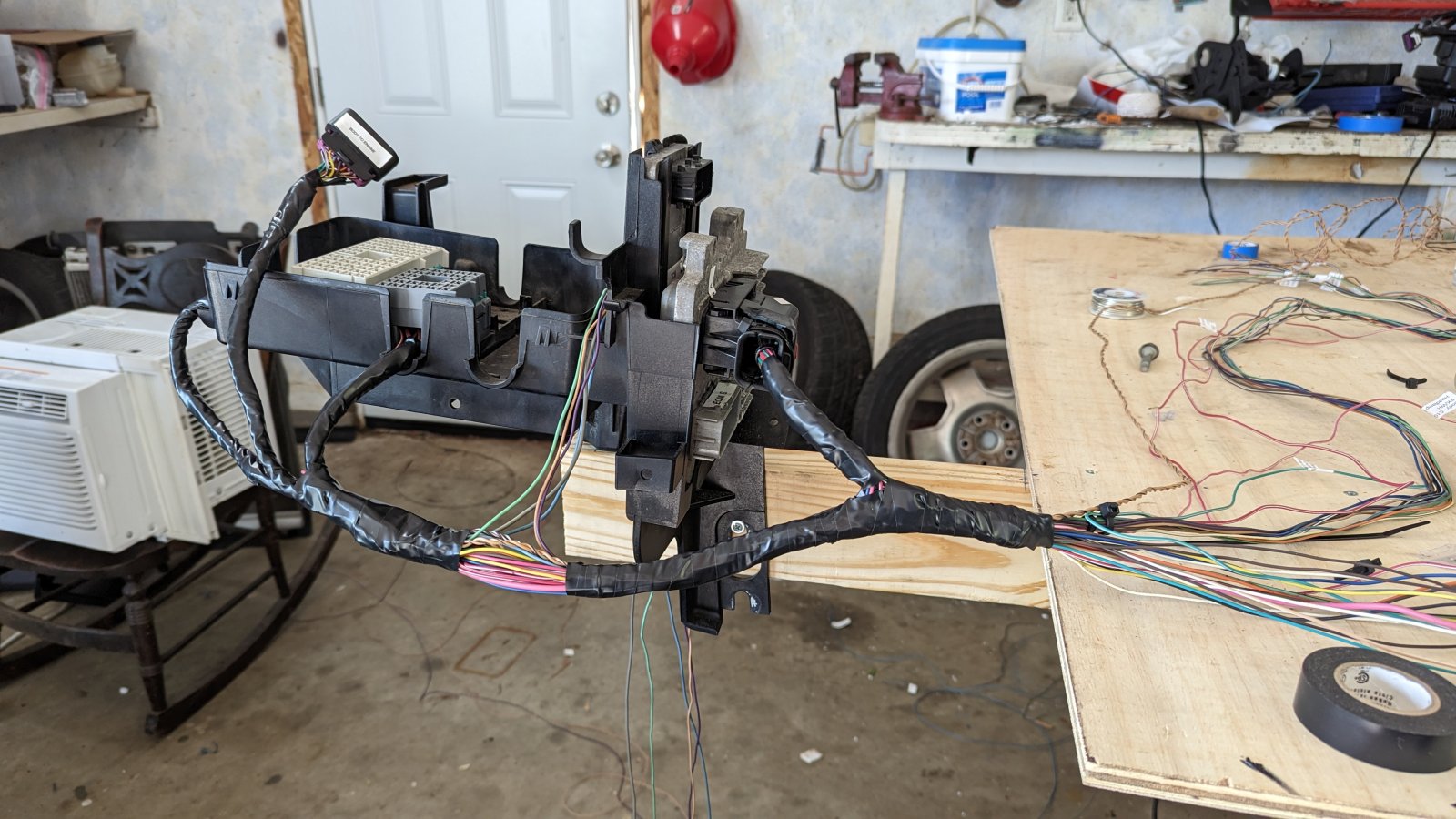
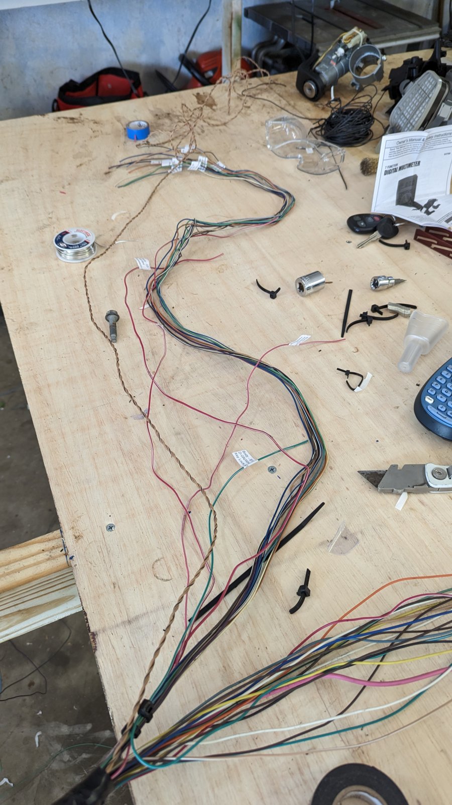
Here's what I got so far
Fenix Nexen
Well-Known Member
- Fenix Nexen Well-Known Member
Made it to the part in the new videos where the headlamp harness is addressed, here is where I am at and correct me if i made a mistake please
So far I have...
Near the fuse block housing is:
3 wires labeled pump that are grey, purple and tan

Black and yellow wires labeled driver tail light and a single green wire labeled passenger tail light

Blue-ish wire labeled center stop light, green wire labeled backup light, black wire labeled driver reflector

Near the BCM end:
Black, grey and white wires with a connector labeled battery current sensor and Yellow/black and green/white ambient temp sensor wires

black or dark gray passenger tail light and reflector wires

and a tan wire in the corner of the red BCM plug that is not labeled

and not pictured is battery cable that is red/black and auto shifter plug
something already does not add up with how i named the lights and which way they are going
So far I have...
Near the fuse block housing is:
3 wires labeled pump that are grey, purple and tan
Black and yellow wires labeled driver tail light and a single green wire labeled passenger tail light
Blue-ish wire labeled center stop light, green wire labeled backup light, black wire labeled driver reflector
Near the BCM end:
Black, grey and white wires with a connector labeled battery current sensor and Yellow/black and green/white ambient temp sensor wires
black or dark gray passenger tail light and reflector wires
and a tan wire in the corner of the red BCM plug that is not labeled
and not pictured is battery cable that is red/black and auto shifter plug
something already does not add up with how i named the lights and which way they are going
Joebob
Goblin Guru
- Joebob Goblin Guru
I found this link incredibly helpful if something went weird or confirming some of the extra wire things I was doing:Made it to the part in the new videos where the headlamp harness is addressed, here is where I am at and correct me if i made a mistake please
So far I have...
Near the fuse block housing is:
3 wires labeled pump that are grey, purple and tan
View attachment 40327
Black and yellow wires labeled driver tail light and a single green wire labeled passenger tail light
View attachment 40328
Blue-ish wire labeled center stop light, green wire labeled backup light, black wire labeled driver reflector
View attachment 40329
Near the BCM end:
Black, grey and white wires with a connector labeled battery current sensor and Yellow/black and green/white ambient temp sensor wires
View attachment 40330
black or dark gray passenger tail light and reflector wires
View attachment 40331
and a tan wire in the corner of the red BCM plug that is not labeled
View attachment 40332
and not pictured is battery cable that is red/black and auto shifter plug
something already does not add up with how i named the lights and which way they are going
V1 - BAR-AIR's build up in Buffalo N.Y.
Yes those are 5 3/4” lenses. Just make sure they are the DOT lenses. Those were advertised as DOT lenses but when they showed up no DOT markings. Took about a month of back and forth with the manufacturer before they sent a set of DOT lenses. Nate’s car is using a set of 5 3/4” headlight shells...
Fenix Nexen
Well-Known Member
- Fenix Nexen Well-Known Member
what gauge is the light blue radiator fan wire?
edit: found it
edit: found it
Last edited:
Fenix Nexen
Well-Known Member
- Fenix Nexen Well-Known Member
someone confirm my research, i looked into what purpose the brown wire serves here as i am confused as why brown wires labeled passenger go up front and the others go to the rear are labeled driver, wondering if it matters?
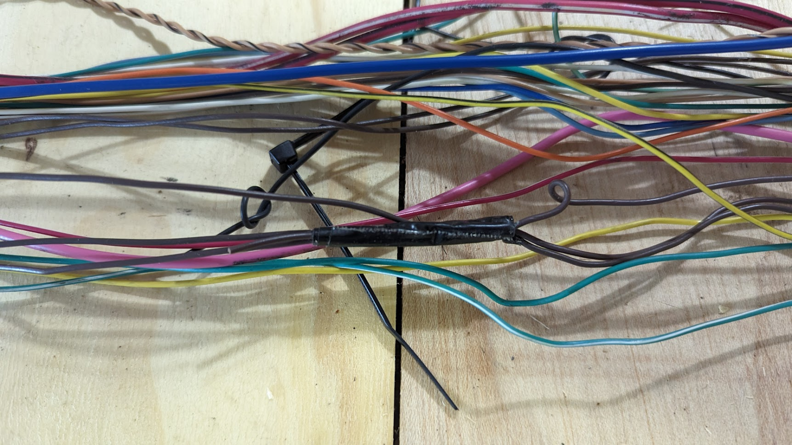
and found diagrams for it possibly
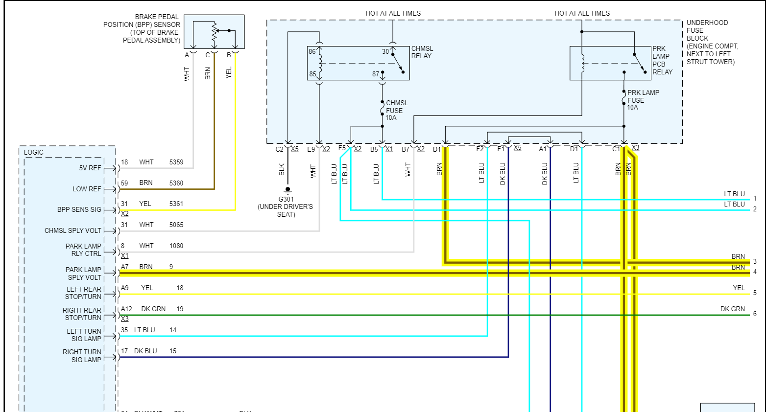
looked up what the park lamp relay does

and found diagrams for it possibly
looked up what the park lamp relay does
Fenix Nexen
Well-Known Member
- Fenix Nexen Well-Known Member
wiring progress, iv read that its a good idea to wait on wrapping up the harness till everything is proven working
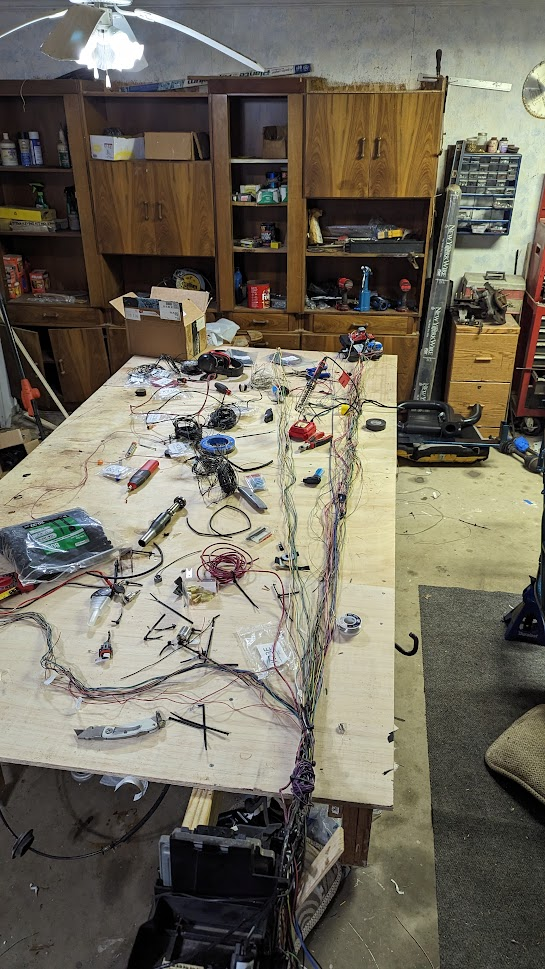
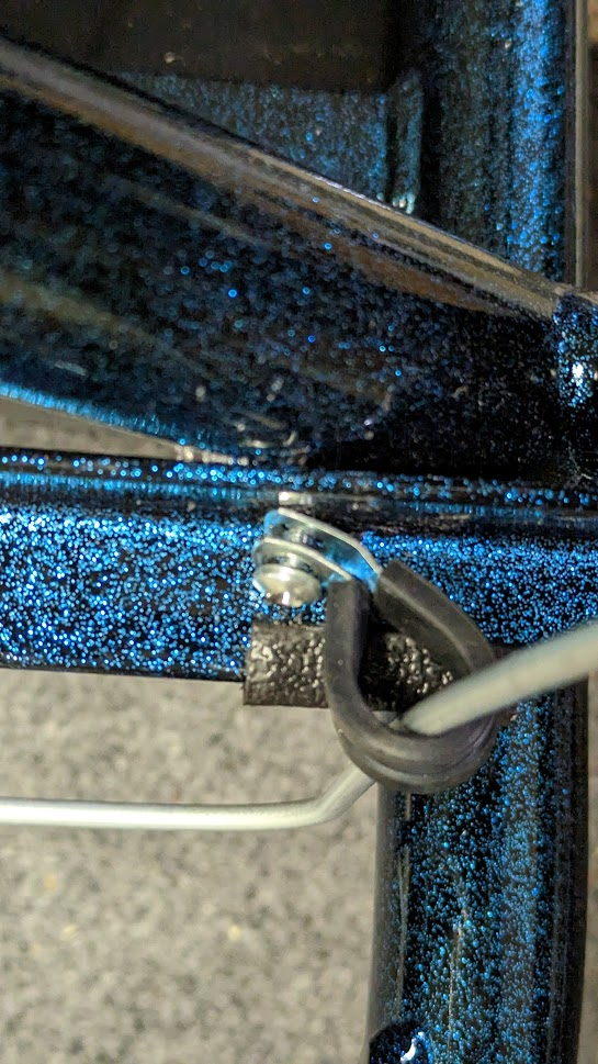
another thing, the self tapping screw walked to the corner and made it impossible to fully go in because of the clamp and became quickly stripped, a tug test says its fine like that
next step is to thin the dash harness
another thing, the self tapping screw walked to the corner and made it impossible to fully go in because of the clamp and became quickly stripped, a tug test says its fine like that
next step is to thin the dash harness
Fenix Nexen
Well-Known Member
- Fenix Nexen Well-Known Member


Rttoys
Smokin' Goblin

- Rttoys Smokin' Goblin
I used loom on the main harness, so I could access it if need be. I would tape it up, so it’s easier to deal with on install.
I like a little bit of wiggle room on the lines so they don’t run through.
I think that’s the wire for accessory power at the dash for optional devices you may want to install. It’s good to have.
I like a little bit of wiggle room on the lines so they don’t run through.
I think that’s the wire for accessory power at the dash for optional devices you may want to install. It’s good to have.
Fenix Nexen
Well-Known Member
- Fenix Nexen Well-Known Member
Safe to assume that the accessory power wire goes straight to the 12v accessory plug?
Fenix Nexen
Well-Known Member
- Fenix Nexen Well-Known Member
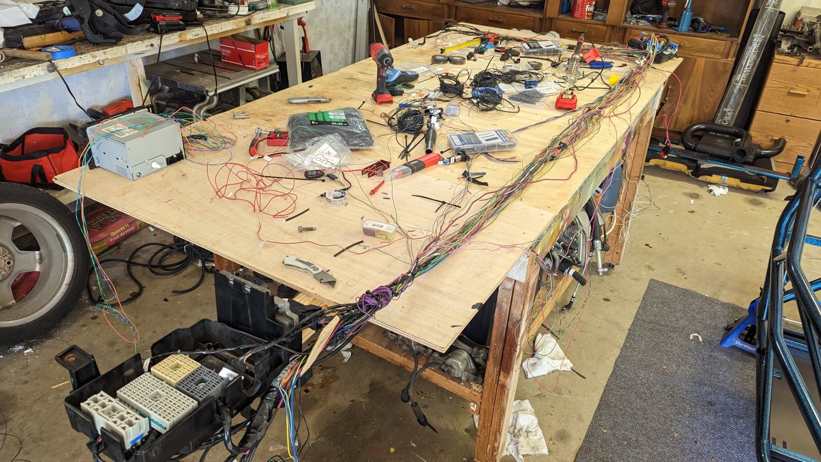
Making progress. Accessory power wire still alludes me
Similar threads


- Replies
- 212
- Views
- 49K
- Replies
- 157
- Views
- 47K


- Replies
- 1K
- Views
- 360K