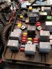
I don't think you can measure resistance end-to-end since you'd be measuring through all of the involved circuit boards. From my understanding the high speed GMLAN is a serial network.
You are correct, the Cobalt uses differential CANbus and a proprietary single ended CANbus, both of which are forms of serial networks. When speaking about the CANbus in question, there is no circuitry isolating one segment of wire from another in the Cobalt - GM just chose to pass the CANbus "in and out" of each module to add complication with little if any up-side. You can most certainly measure the resistance end to end as it is just a "Wire". There are vehicles that do isolate network segments into broadcast domains using gateway modules. -the Cobalt is not one.
Background:
Differential CANbus is simply a parallel network architecture that uses a bus topology. The normal layout is each module taps into the bus with two wires. GM decided to actually pass the wiring
through the various modules. If you use a meter, you will see there is a dead short between the in and out of each CANbus lead on all the modules. This implementation has little advantage and many disadvantages.
You can choose to re-arrange the network layout or even abandon the "in and out" method used by GM all together and the bus will still work. Ideally you still want to maintain a network where you have a terminating resistor at the beginning and end of the network. In the case of the Cobalt, the terminating resistors are in the PSCM and the ECM. The diagnostic connector does not have any active electronics so it does not count, and the only other module the Goblin uses is the BCM and in some cases, the RPD. So these two modules need to ideally stay in the middle of the network.
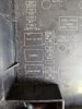
Bold below indicates a module with a terminating resistor.
DLC<--->
PSCM<--->(RPD)<--->BCM<--->
ECM