Jim McDonald // Extended Track // '09 HHR SS/TC Automatic
- Thread starter Torchandregdoc
- Start date
KSLunsfo
Well-Known Member
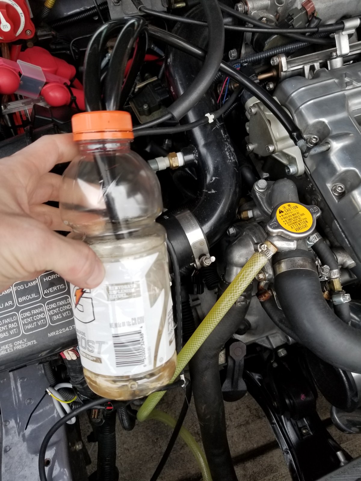
An improperly set up system will definitely lose oil into the cans, a properly installed system will not. Baffles stand between keeping or losing oil into the catch cans. This is what methinks/knows. Last I messed with my eclipse I was performing a bit of a temporary experiment with a Gatorade bottle as a catch can, literally... I will take a picture of what's in it this evening. It has a few weeks of driving occasionally worth of 'stuff'. You will see how clear the fluid is.Is a catch-can setup simply a way of removing from the engine perfectly good oil 99.9 percent of which would have stayed in the crankcase if the PCV valve had not been blocked off? In the case of boosted Ecotecs, especially those with low mileage and healthy piston rings, methinks yes.
KSLunsfo
Well-Known Member
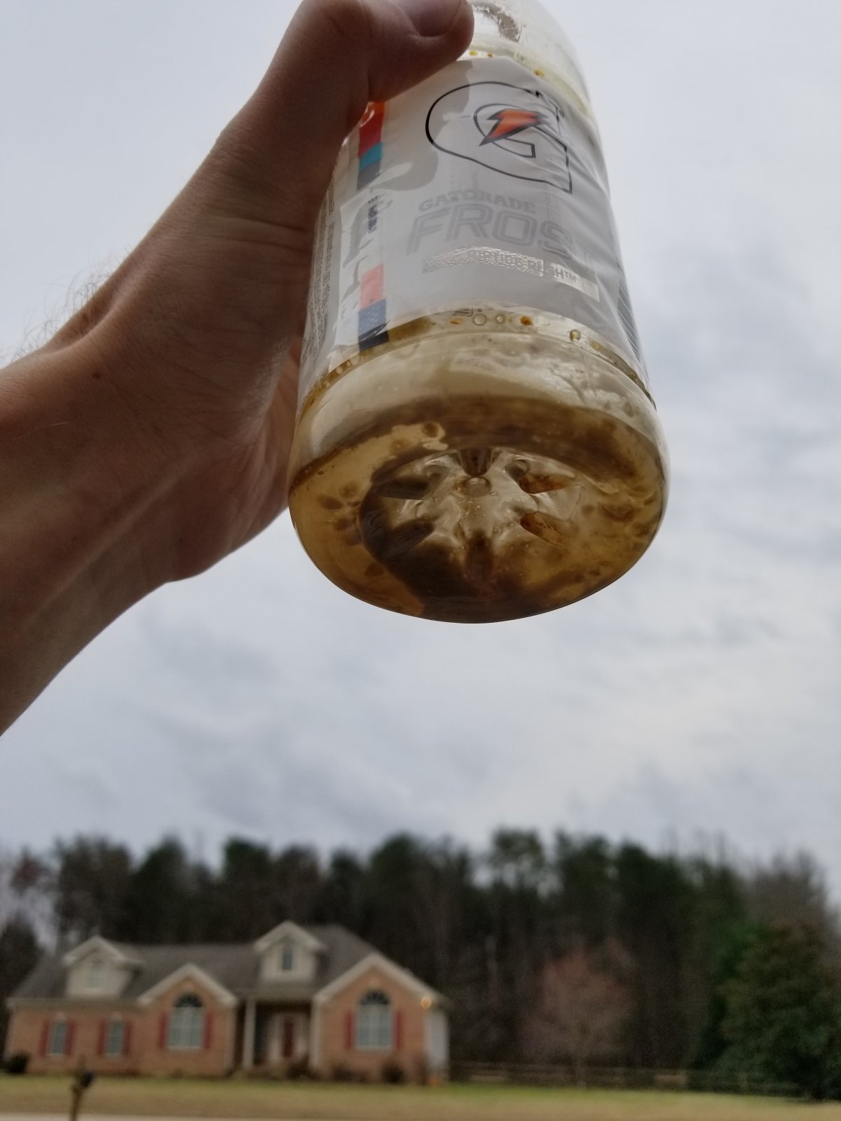
Here's pictures from the crude test on my turbo eclipse. This is a few weeks of occasional driving as it's not my daily driver. There's about a 1/4" of what looks like dirty water in the bottle. Of course this is not an eco friendly setup as the second hose just runs under the car, so any airborne particles just blows under the car. This car has NO PCV and I have boosted to ~30psi numerous times with a gatorade bottle as a 'catch can'. I have a nice, permanent catch can setup, this was just a goofy experiment I wanted to conduct.
Torchandregdoc
Goblin Guru
It stores vacuum to be used at another time. There is a check valve inside the canister that holds vacuum pulled by the hose on the left of your picture.Until I understand every working component of the system, I am not comfortable making changes. But like you, I WANT to get rid of / decrease the amount of oil getting to the intake.
I stumbled on the thread below this morning. In addition to the routing above in your diagram from the intake manifold, there is a vacuum tank? (pic below is from my engine) What purpose does it serve? The guy in this thread removed it from the system. Post #40 has a link to a pic.
https://www.cobaltss.net/forums/2-0l-lnf-performance-tech-153/bypass-valve-fix-possible-boost-mod-191361/index2.html
View attachment 11920
Desert Sasqwatch
Goblin Guru
I've been watching all of the conversations, in multiple threads, on the 'philosophies' of oil separation/catch cans and the theories of how to minimize oil getting into the turbo/intercooler/intake manifold. We all know this is not an ideal situation for any engine and results in less than ideal conditions from carbon build up and loss of performance.
For NA engines, setting up an oil separation system is much simpler than a boosted engine by putting a catch can between the valve cover outlet and the vacuum port on the intake manifold. For a SC or TC engine, which should in practice require the same basic set up, requires addressing both the vacuum side and the boost side of the intake system.
The following are my thoughts on an answer to the TC engine, since this is what I have, and is the path I believe I will be following - unless some other information that contradicts my solution theory is posted. This is not THE solution, as I am sure there is more than way to resolve this issue, and I'm sure others have their own opinions on whether this solution would work for them or not.
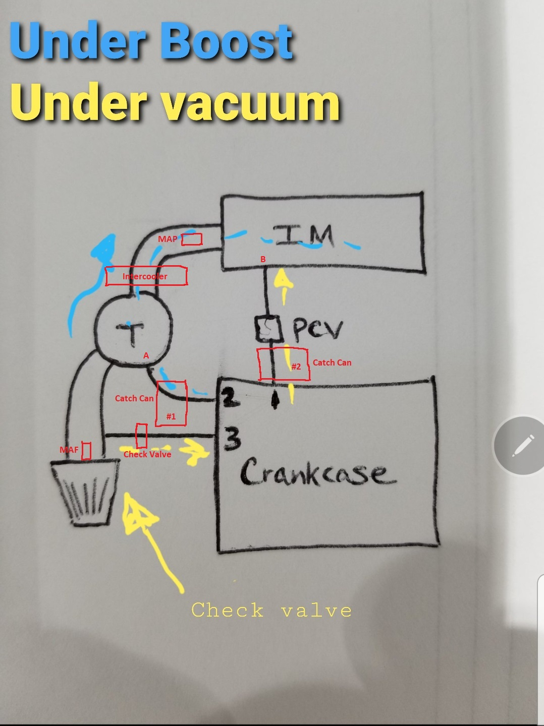
Pirating from KSLunsfo's original TC diagram and the edit from Torchandregdoc I have added to it to show what I am explaining in my theory:
-The filtered air input at (3) in the valve cover needs to be pulled off after the MAF, so it is 'metered' and accounted for by the ECM in the total air volume entering the engine. I believe this is the way the factory intake tube port is split off to go to the valve cover thru a check valve. I am on the fence if the check valve is needed for this line or not, but understanding that blow-by, especially under boost, can create a good amount of crankcase pressure that could force its way backward into the intake tube if no check valve is installed.
-The turbo port (A) is always under vacuum when the engine is running and the intake manifold port (B) will vary between vacuum (off throttle) and boost pressure (on throttle). These are the two sides of the system that need to be kept separate with any solution.
-Because (A) is under vacuum, a catch can #1 should be installed between (2) in the valve cover and the turbo intake port to eliminate as much oil vapor from entering the turbo as possible. This oil vapor may or may not coke up the intake turbine, but it will find its way into the intercooler, where it will condense into liquid, and contaminate the interior that reduces cooling efficiency. It can also affect the MAP sensor and, in the extreme, end up in the intake manifold.
-Port (B) under boost will be blocked by the PCV to prevent boost pressure from bleeding back into the crankcase. Under vacuum the port (B) will pull oil vapor from the engine into the intake manifold. Assuming the PCV functions correctly, catch can #2 should be installed between (1) and the intake manifold to capture this oil vapor. I believe this is the source of the majority of the oil being found in the intake manifold, as described by many, and adding this catch can will significantly reduce it.
My solution requires two catch cans, since the two sides of the intake system - before the turbo and after the turbo - must be kept separate to prevent messing up the air metering of the ECM and potential cross bleed of boost/vacuum. I also believe it is important to keep the (1), (2) and (3) port/line sizes close to the factory sizes - for a stock tune - to prevent messing up the 'expected' air metering for the system.
For NA engines, setting up an oil separation system is much simpler than a boosted engine by putting a catch can between the valve cover outlet and the vacuum port on the intake manifold. For a SC or TC engine, which should in practice require the same basic set up, requires addressing both the vacuum side and the boost side of the intake system.
The following are my thoughts on an answer to the TC engine, since this is what I have, and is the path I believe I will be following - unless some other information that contradicts my solution theory is posted. This is not THE solution, as I am sure there is more than way to resolve this issue, and I'm sure others have their own opinions on whether this solution would work for them or not.
Pirating from KSLunsfo's original TC diagram and the edit from Torchandregdoc I have added to it to show what I am explaining in my theory:
-The filtered air input at (3) in the valve cover needs to be pulled off after the MAF, so it is 'metered' and accounted for by the ECM in the total air volume entering the engine. I believe this is the way the factory intake tube port is split off to go to the valve cover thru a check valve. I am on the fence if the check valve is needed for this line or not, but understanding that blow-by, especially under boost, can create a good amount of crankcase pressure that could force its way backward into the intake tube if no check valve is installed.
-The turbo port (A) is always under vacuum when the engine is running and the intake manifold port (B) will vary between vacuum (off throttle) and boost pressure (on throttle). These are the two sides of the system that need to be kept separate with any solution.
-Because (A) is under vacuum, a catch can #1 should be installed between (2) in the valve cover and the turbo intake port to eliminate as much oil vapor from entering the turbo as possible. This oil vapor may or may not coke up the intake turbine, but it will find its way into the intercooler, where it will condense into liquid, and contaminate the interior that reduces cooling efficiency. It can also affect the MAP sensor and, in the extreme, end up in the intake manifold.
-Port (B) under boost will be blocked by the PCV to prevent boost pressure from bleeding back into the crankcase. Under vacuum the port (B) will pull oil vapor from the engine into the intake manifold. Assuming the PCV functions correctly, catch can #2 should be installed between (1) and the intake manifold to capture this oil vapor. I believe this is the source of the majority of the oil being found in the intake manifold, as described by many, and adding this catch can will significantly reduce it.
My solution requires two catch cans, since the two sides of the intake system - before the turbo and after the turbo - must be kept separate to prevent messing up the air metering of the ECM and potential cross bleed of boost/vacuum. I also believe it is important to keep the (1), (2) and (3) port/line sizes close to the factory sizes - for a stock tune - to prevent messing up the 'expected' air metering for the system.
Last edited:
Torchandregdoc
Goblin Guru
I'm just now understanding, 30 years post, why school was so hard for me. I pulled decent grades, but it was a struggle every inch of the way. A+ in statics, C in dynamics. I'm a visual learner. Love this drawing.I've been watching all of the conversations, in multiple threads, on the 'philosophies' of oil separation/catch cans and the theories of how to minimize oil getting into the turbo/intercooler/intake manifold. We all know this is not an ideal situation for any engine and results in less than ideal conditions from carbon build up and loss of performance.
For NA engines, setting up an oil separation system is much simpler than a boosted engine by putting a catch can between the valve cover outlet and the vacuum port on the intake manifold. For a SC or TC engine, which should in practice require the same basic set up, requires addressing both the vacuum side and the boost side of the intake system.
The following are my thoughts on an answer to the TC engine, since this is what I have, and is the path I believe I will be following - unless some other information that contradicts my solution theory is posted. This is not THE solution, as I am sure there is more than way to resolve this issue, and I'm sure others have their own opinions on whether this solution would work for them or not.
Pirating from KSLunsfo's original TC diagram and the edit from Torchandregdoc I have added to it to show what I am explaining in my theory:
-The filtered air input at (3) in the valve cover needs to be pulled off after the MAF, so it is 'metered' and accounted for by the ECM in the total air volume entering the engine. I believe this is the way the factory intake tube port is split off to go to the valve cover thru a check valve. I am on the fence if the check valve is needed for this line or not, but understanding that blow-by, especially under boost, can create a good amount of crankcase pressure that could force its way backward into the intake tube if no check valve is installed.
-The turbo port (A) is always under vacuum when the engine is running and the intake manifold port (B) will vary between vacuum (off throttle) and boost pressure (on throttle). These are the two sides of the system that need to be kept separate with any solution.
-Because (A) is under vacuum, a catch can #1 should be installed between (2) in the valve cover and the turbo intake port to eliminate as much oil vapor from entering the turbo as possible. This oil vapor may or may not coke up the intake turbine, but it will find its way into the intercooler, where it will condense into liquid, and contaminate the interior that reduces cooling efficiency. It can also affect the MAP sensor and, in the extreme, end up in the intake manifold.
-Port (B) under boost will be blocked by the PCV to prevent boost pressure from bleeding back into the crankcase. Under vacuum the port (B) will pull oil vapor from the engine into the intake manifold. Assuming the PCV functions correctly, catch can #2 should be installed between (1) and the intake manifold to capture this oil vapor. I believe this is the source of the majority of the oil being found in the intake manifold, as described by many, and adding this catch can will significantly reduce it.
My solution requires two catch cans, since the two sides of the intake system - before the turbo and after the turbo - must be kept separate to prevent messing up the air metering of the ECM and potential cross bleed of boost/vacuum. I also believe it is important to keep the (1), (2) and (3) port/line sizes close to the factory sizes - for a stock tune - to prevent messing up the 'expected' air metering for the system.
View attachment 11925
Desert Sasqwatch
Goblin Guru
Jim, The one thing I did not discuss in detail is the factory PCV inside the intake manifold would need to be bypassed - plugged - and an external loop for the catch can and external PCV would be needed. Basically, plugging the PCV hole from the crankcase but still using the original PCV port in the manifold with the external loop. This complicates the 'simpleness' of the drawing at (B) from the crankcase to the intake manifold, but is key to removing the direct path of oil/vapor getting into the manifold.
Last edited:
Torchandregdoc
Goblin Guru
Thanks for the input Tim. I understood what you meant in your pic. Every thing in red is new, well, except the check valve, that already exists, although I haven't studied (looked at pics) how and where that line attaches on a goblin, post air cleaner but pre-MAF.Jim, The one thing I did not discuss in detail is the factory PCV inside the intake manifold would need to be bypassed - plugged - and an external loop for the catch can and external PCV would be needed. Basically, plugging the PCV hole from the crankcase but still using the original PCV port in the manifold with the external loop. This complicates the 'simpleness' of the drawing at (B) from the crankcase to the intake manifold, but is key to removing the direct path of oil/vapor getting into the manifold.
This whole topic really got started in my head when I was trying to figure out how to put a Saab 9-3 intake manifold on my LNF in order to reduce and uncomplicate charge piping. I haven't put the motor back in the car since I got the fuel tank back, but I'm reasonably sure I will have a conflict in space between the charge pipe and tank.
Ross
Goblin Guru
Does a PCV valve act as a check valve too? Therefor stopping venting on port #1 when in boost?
So what is there to stop port #2 from venting under both boost and vacuum?
Briann1177
Goblin Guru
The PCV inside the intake is supposed to close under boost. Also, there is always a negative pressure on port 2 due to the turbo air flow over it. Venturi effect. People who smoke in their cars are very familiar with this effect.
Torchandregdoc
Goblin Guru
Ross, yes, the PCV valve is just a check valve.Does a PCV valve act as a check valve too? Therefor stopping venting on port #1 when in boost?
So what is there to stop port #2 from venting under both boost and vacuum?
So, under Boost, the check/PCV Valve #1 closes and the vacuum affect/effect at the turbo pulls fresh clean air mixed with vapors through #2.
Under vacuum, throttle closed, (yes, I know you know when vacuum is produced), air will feed into the engine through 1&2. My guess is there is still some vacuum pulled through 2 into the turbo during throttle closed times, but I may be wrong there. The turbo recycle valve would be open then and in theory charge air wiuld just be cycling thought the turbo and then back through the turbo.
Torchandregdoc
Goblin Guru
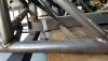
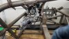
Do any of you wish this cross member was further forward or gone? I'm fitting and welding today and I have mixed reviews here. The reviews are by kids though and looking for a second opinion.
Attachments
-
 185.1 KB Views: 353
Karter2026
Goblin Guru
I never had any issues. It does help hold the floor mat I cut for it in place.
Torchandregdoc
Goblin Guru
Is this clocked correctly? Looks like its going to be in the way.
Attachments
-
 202.5 KB Views: 319
Waterdriver
Goblin Guru
The motor should be at horizontal.
Your power steering unit looks a little different i think than my 05 Cobalts though.
Your power steering unit looks a little different i think than my 05 Cobalts though.
Last edited:
Torchandregdoc
Goblin Guru
Ok. Looks like your ps motor is smaller also. Looks Like the HHR PS assy is different.
Torchandregdoc
Goblin Guru
Can anyone get me a dimension on the shaft length. I would just go get a Cobalt PS unit, but I'm not sure how well the HHR electronics will communicate with the Cobalt steering.
Waterdriver
Goblin Guru
I would ask Lonny and Adam to see if they could make you an HHR mounting bracket that would index your PS unit.
It would help them to make the HHR a viable donor option in the future.
It would help them to make the HHR a viable donor option in the future.