Ark's City Goblin #187 (2008 SS/TC donor)
- Thread starter Ark :D
- Start date

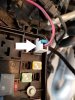
No, The connection at the battery with the 50 amp fuse powers the BCM directly. The connector at the fuse box you are pointing to is for the power steering.Ok, this may be a much easier fix that I thought, if my memory serves me well (probably not!) ... but the connection right after the 50A fuse near the battery leads to the pictured connector on the fuse box, right?
View attachment 14918View attachment 14919
Ark :D
Goblin Guru
Fixed that for you.I thinkyouother amazing contributors found the problem.
Sanity check me, please. I'm going looney from tracing wires, and I feel like the solution really CAN'T be this easy.
These two connectors should have continuity, right?
Yes, they should have continuity. Power from the battery to the inline connector. From the inline connector to the inline 50 amp fuse. From the fuse to the BCM1 input (BCM X3 D4) as shown in your picture. This powers many of the circuits at the BCM. This would NOT cause an issue with power at pins 3, 5 and 6 as they are powered from the main fuse block.
Attachments
-
 52.1 KB Views: 211
Ark :D
Goblin Guru
I decided to take a breather from the wiring for the evening. **** is driving me batty. Fairly confident at this point that my BCM doesn't have power. Not positive on that, but I'll find out tomorrow.
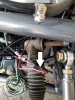
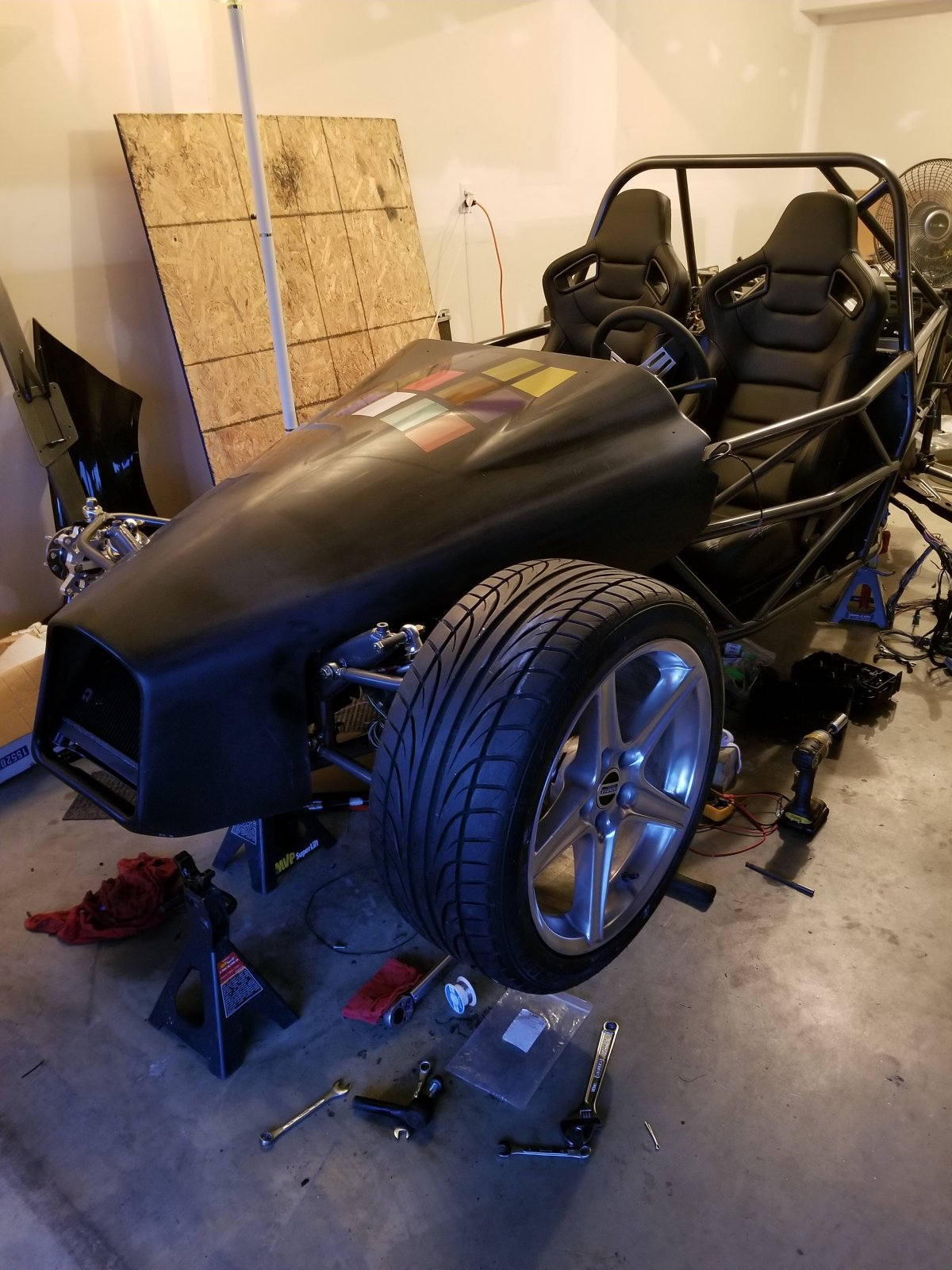
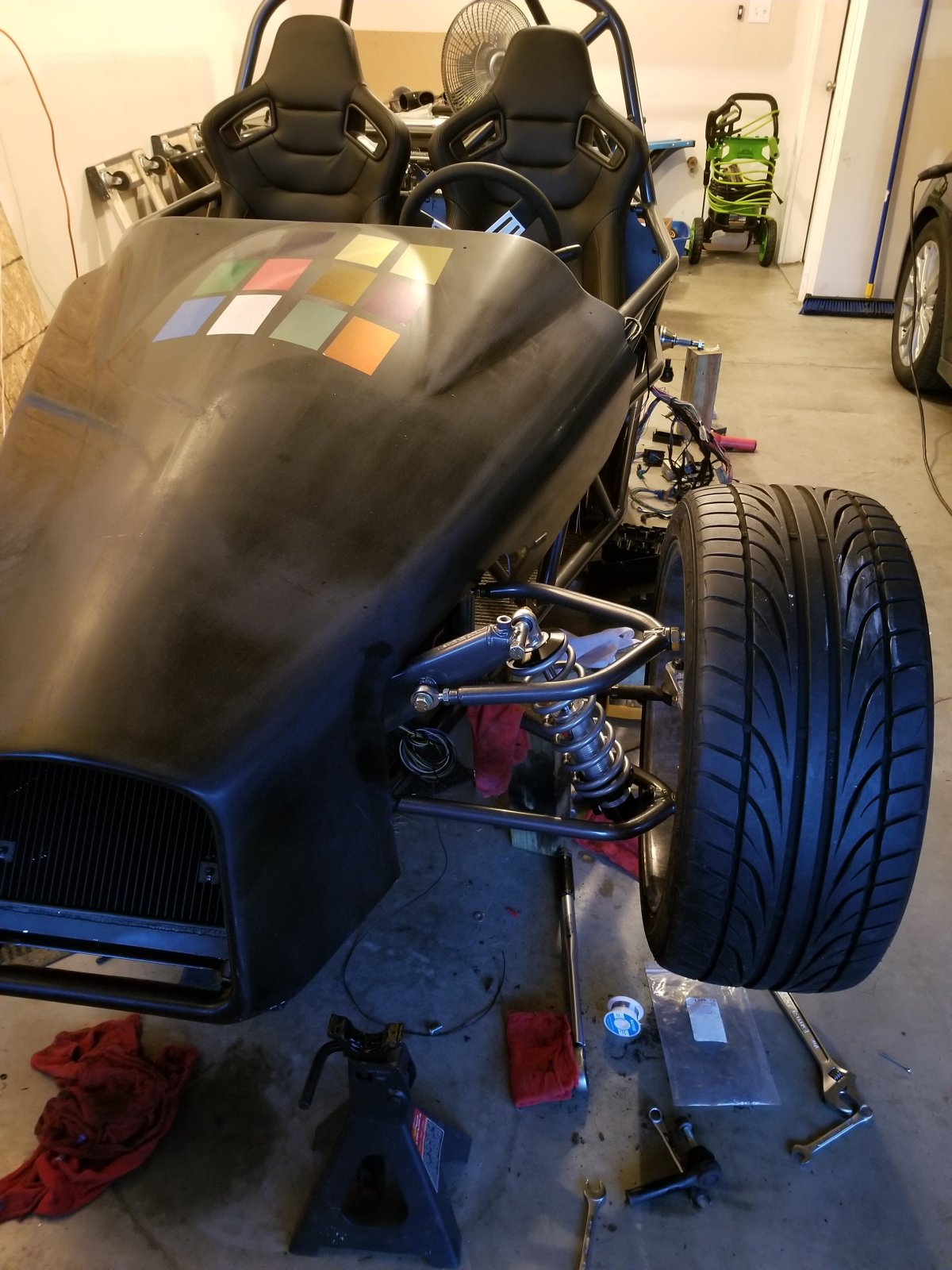
So tonight, like I said, I took a break from the wiring. I figured I'd get the front suspension on and maybe get the car down on the front two wheels. That turned out to be a bit ambitious, because I ended up cooking dinner for my family (I'm a much better cook than I am a Goblin builder!), so I lost some time there. Also, I do not have the right size socket to tighten down the big bolts on the top and bottom of the uprights, so I'll have to go buy one tomorrow.
A sneak preview will have to do, for now. Back on it tomorrow.
Last edited:
Now I am confused. Both the text in one of my previous posts and the BCM layout I provided in post 507 indicate exactly what you think - pin 56 should get power from the BCM1 circuit which in turn gets power from the large red wire feeding BCM X3 D4. What I had mentioned before is that the power for the large 3 wires at X2 on the PCM get their power directly from the fuse box. Hopefully this helps, if not, let me know.My wire tracing says that pin 56 in the ECM connector winds up in the red BCM plug and pulls power from the large red/black wire in the corner. You're saying otherwise, so you're probably right. My head is spinning with the wiring right now.
Ark :D
Goblin Guru
Now I am confused. Both the text in one of my previous posts and the BCM layout I provided in post 507 indicate exactly what you think - pin 56 should get power from the BCM1 circuit which in turn gets power from the large red wire feeding BCM X3 D4. What I had mentioned before is that the power for the large 3 wires at X2 on the PCM get their power directly from the fuse box. Hopefully this helps, if not, let me know.
Ark :D
Goblin Guru
After a good night of sleep, I'm now fresh as a daisy, or something like that.
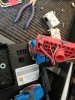
I hopped back on the wiring this morning. To recap, yesterday I started with pin 56 in the ECM connector, which according to Bradr, should have 12v at all times. It did not, so I traced back through the wiring to see where circuit was failing. I traced it all the way back to the BCM, which was not getting power. I undid my wrapping on the harness in that general area (side note: tesa tape is amazing, until you need to unwrap it) and found that, probably while bending and contorting my harness to fit it into the frame, my solder on the big BCM power wire had cracked/broken. I grabbed a new crimp jacket and fixed it. Then I tested with my multimeter, and my BCM has power.
Side question: if my BCM did not have power, how was my cluster displaying my mileage?
Regardless, I went to the rear of the car and reconnected everything. I used my multimeter to test for 12v on pin 56 of the ECM connector. I was surprised to see now, there is a minor NEGATIVE current draw on that pin, and on pins 3, 5, and 6. I'm talking like, in the range of 10-20 millivolts.
So I defer to people that understand electricity better than myself. What does this mean?
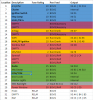
Take a look at my diagram in post 507. You will see that the BCM is actually divided up internally into 4 major circuits. The large wire with the 50 amp fuse you had an issue with, would have only caused an issue with the circuits powered by that supply. The instrument cluster is powered from the BCM 2 circuit, thus the reason why it worked.Side question: if my BCM did not have power, how was my cluster displaying my mileage?
Test for voltage at:Regardless, I went to the rear of the car and reconnected everything. I used my multimeter to test for 12v on pin 56 of the ECM connector. I was surprised to see now, there is a minor NEGATIVE current draw on that pin, and on pins 3, 5, and 6. I'm talking like, in the range of 10-20 millivolts.
So I defer to people that understand electricity better than myself. What does this mean?
- Both sides of fuse 25 (10A ECM/TCM) at the BCM - You should have 12v all the time
- Both sides of the 20A "PCM/ECM" at the fuse box - You should have 12 with the ignition on (I PREVIOUSLY SAID THIS SHOULD BE 12V ALL THE TIME - I MISSPOKE AND EDITED MY PREVIOUS POST)
Briann1177
Goblin Guru
Not to be a smart ass, but that probably means you have your meter leads hooked up backwards. Doing current checks isn't really that useful. At least in this case. I think you're still trying to figure out if things are getting voltage or not.So I defer to people that understand electricity better than myself. What does this mean?
Ark :D
Goblin Guru
Outside contact of fuse 25 in BCM: +12vTake a look at my diagram in post 507. You will see that the BCM is actually divided up internally into 4 major circuits. The large wire with the 50 amp fuse you had an issue with, would have only caused an issue with the circuits powered by that supply. The instrument cluster is powered from the BCM 2 circuit, thus the reason why it worked.
Test for voltage at:
- Both sides of fuse 25 (10A ECM/TCM) at the BCM - You should have 12v all the time
- Both sides of the 20A "PCM/ECM" at the fuse box - You should have 12 with the ignition on (I PREVIOUSLY SAID THIS SHOULD BE 12V ALL THE TIME - I MISSPOKE AND EDITED MY PREVIOUS POST)
Inside contact of fuse 25 in BCM: 10-20 millivolts
Both contacts of 20A "PCM/ECM" fuse: no voltage
At this point, I could be doing anything wrong, I realize that. But, I just re-tested, ensuring that I am not reversing the probes on my meter.Not to be a smart ass, but that probably means you have your meter leads hooked up backwards. Doing current checks isn't really that useful. At least in this case. I think you're still trying to figure out if things are getting voltage or not.
ctuinstra
Goblin Guru
Looks like that fuse is blown. You should measure the same on both sides of a fuse (with respect to ground).Outside contact of fuse 25 in BCM: +12v
Inside contact of fuse 25 in BCM: 10-20 millivolts
So fuse 25 at the BCM is blown. Replace it and that should be enough to get the PCM communicating with the rest of the car.Outside contact of fuse 25 in BCM: +12v
Inside contact of fuse 25 in BCM: 10-20 millivolts
Please note: This issue will likely be resolved by fixing the fuse above!Both contacts of 20A "PCM/ECM" fuse: no voltage
Lack of power at the 20 A PCM/ECM fuse, this is either an issue with the powertrain relay, or more likely the relay is not being triggered by the BCM. There should be a yellow wire running from X2, 58 at the PCM to X5, E2 of the fuse box. This wire applies a ground to the PWR/TRN relay, in turn supplying power to the 3 wires at the PCM. You should see this wire have about 12v until the ignition is turned on. Check both ends of the wire if necessary.
Ark :D
Goblin Guru
I tested with the fuse pulled. With the fuse in, both sides show +12v.Looks like that fuse is blown. You should measure the same on both sides of a fuse (with respect to ground).
Working on testing this now.Please note: This issue will likely be resolved by fixing the fuse above!
Lack of power at the 20 A PCM/ECM fuse, this is either an issue with the powertrain relay, or more likely the relay is not being triggered by the BCM. There should be a yellow wire running from X2, 58 at the PCM to X5, E2 of the fuse box. This wire applies a ground to the PWR/TRN relay, in turn supplying power to the 3 wires at the PCM. You should see this wire have about 12v until the ignition is turned on. Check both ends of the wire if necessary.
Waste of time - if the PCM never powers up, it can never command the PWR/TRN relay to turn on. You need to resolve the other issue (lack of constant power at PCM X2 56) first. As I said above, there likely is no issue with the lack of power at pins 3/5/6.Working on testing this now.
If the fuse is good, check for power, in order, at:I tested with the fuse pulled. With the fuse in, both sides show +12v.
- BCM X3, D4
- Fuse Block X5, E4
- Fuse Block X5, E3
- PCM X2, 56
Note: The connection to the fuse block has no value in yuor car and can be bypassed if the issue is found to be there.