
-
We've upgraded and reskinned the forum. Notice something off? Email us at [email protected] and we'll fix it.
You are using an out of date browser. It may not display this or other websites correctly.
You should upgrade or use an alternative browser.
You should upgrade or use an alternative browser.
V1 Matt3458's Daily Goblin - 2006 SS/SC #480


Matt3458
Active Member

- Matt3458 Active Member
Congrats on getting your RO license. I'm an auxiliary operator at Catawba nuclear and just picked up my chassis #474. Have an 07 ss/sc donor. Excited to get started. Looks like you are a few months ahead of me.
Thanks. Good luck to you, it's hard to find time to work on the car between rotating shifts and summer heat.

Desert Sasqwatch
Bigfoot Goblin

- Desert Sasqwatch Bigfoot Goblin
Not just summer heat - Phoenix heat!!! We've been smoking hot for weeks and garage work is rare when the day starts at 95 degrees just before sun rise! And the garage doesn't cool down from 100+ unless you're cheating with an air conditioner!Thanks. Good luck to you, it's hard to find time to work on the car between rotating shifts and summer heat.


Goblinfanclub1234
Goblin Guru

- Goblinfanclub1234 Goblin Guru
mine was similar I think you will find this in any clapped out ss hahahaFor anyone needing a laugh today, here's the results of three people putting three different sound systems
Matt3458
Active Member
- Matt3458 Active Member
Donor teardown is complete and the shell is gone. I've starting working on the wiring harness now. It's slow going due to the differences between my donor and the video's. Most of the extra things in the video get cut out anyway and the wiring diagrams help with most of the rest. I'm a little worried about the layout of the harness at the fuse box (approx 3:30 in Part 4) because my connectors and wires are slightly different.
I do have a question on the fuel pump: right at the start of the Part 3 video, the large gray, small tan, and small purple wires are cut of the fuel pump, tied in a knot, and draped over the fuse box for later. But at the end of Part 4, all he has is the gray and purple wires ("two wires that will be used for the fuel pump" Part 4 7:45). What happened to the tan wire? It looks like it's there at 3:17 but it's gone at 7:10.
I do have a question on the fuel pump: right at the start of the Part 3 video, the large gray, small tan, and small purple wires are cut of the fuel pump, tied in a knot, and draped over the fuse box for later. But at the end of Part 4, all he has is the gray and purple wires ("two wires that will be used for the fuel pump" Part 4 7:45). What happened to the tan wire? It looks like it's there at 3:17 but it's gone at 7:10.
Attachments

Matt3458
Active Member
- Matt3458 Active Member
Thanks Robinjo.
Spent most of the night working on the harness. One final issue and I'm taking a break. In Part 5 we tape up the grounds on the headlight harness. Specifically, it looks like the thick ground in the video connecting the multiplug to the ground bundle with the harness is significantly longer than mine is. (The video wraps a foot of wire from the ground lug. There's less than foot between the lug and the plug.) How important is the spacing for the ground lugs? Should I extend this wire before continuing?
Spent most of the night working on the harness. One final issue and I'm taking a break. In Part 5 we tape up the grounds on the headlight harness. Specifically, it looks like the thick ground in the video connecting the multiplug to the ground bundle with the harness is significantly longer than mine is. (The video wraps a foot of wire from the ground lug. There's less than foot between the lug and the plug.) How important is the spacing for the ground lugs? Should I extend this wire before continuing?
Attachments


Robinjo
Goblin Guru

- Robinjo Goblin Guru
I think this one mounts under the fuse box on the rear stud. I don't remember having to extend that one but it can be a little tight in that region.
One thing I did that might help you out on the ground lugs. You going to have a few clusters of ground lugs in various places close to wrapping up the whole harness. I recommend making sets of wires that interconnect to each of the ground lug clusters. That way, every ground set is connected to all the other ones via a wire. The Cobalt and Goblin's are very (very) sensitive to grounding issues and this little trick helps.
One thing I did that might help you out on the ground lugs. You going to have a few clusters of ground lugs in various places close to wrapping up the whole harness. I recommend making sets of wires that interconnect to each of the ground lug clusters. That way, every ground set is connected to all the other ones via a wire. The Cobalt and Goblin's are very (very) sensitive to grounding issues and this little trick helps.
Matt3458
Active Member
- Matt3458 Active Member
Dove back into the wiring harness after many long night shifts and a weekend in Chicago. Spent most of the day on it, started about halfway in Part 6 and am almost done with Part 9. Figured I’d add my jumbled thoughts and differences between the videos and my ’06 SS/SC.
Part 5 step 17 – my daytime running lights had a light blue and dark blue wires, not purple. Not an issue, just a difference.
Part 5, step 20 – Difference ground layout meant I couldn’t match the harness shape. See post #30. May have to redo later.
Part 6, step 19 – typo on the video overlay, says light blue but should be light green.
Part 8 – I do not have passenger airbag light connector (step 7), traction control connector (step 12), or steering angle connector (step 22). Finding all the audio connectors was a crapshoot (see post #22).
Part 8 – I wanted to keep both the 12 volt outlets wired, but this one gets completely cut out when the C201 dash connector is removed. I’m keeping the plug to see if I can get power somewhere else.
Part 9, step 24 – I had to solder extensions to 3 wires in order to get the 7 inches for the dash cluster connector. I figure I’d rather be long than short and doing it now is easier than when it’s in the car.
Thing’s I’ve found helpful:
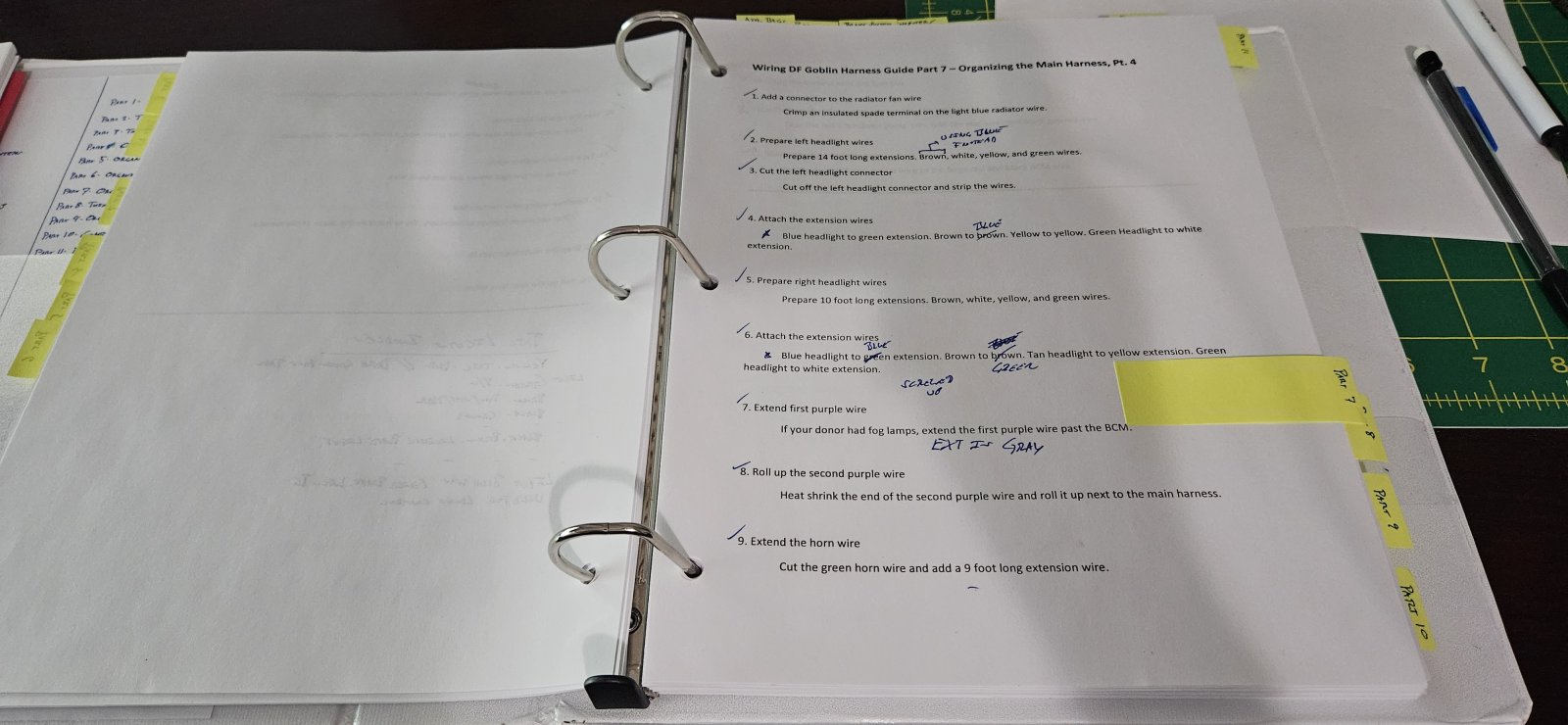
I printed out a transcript of the videos. Just the step title overlays, but it helps keep track of where I’m at and finding when looking ahead or back. It also is great for taking notes.
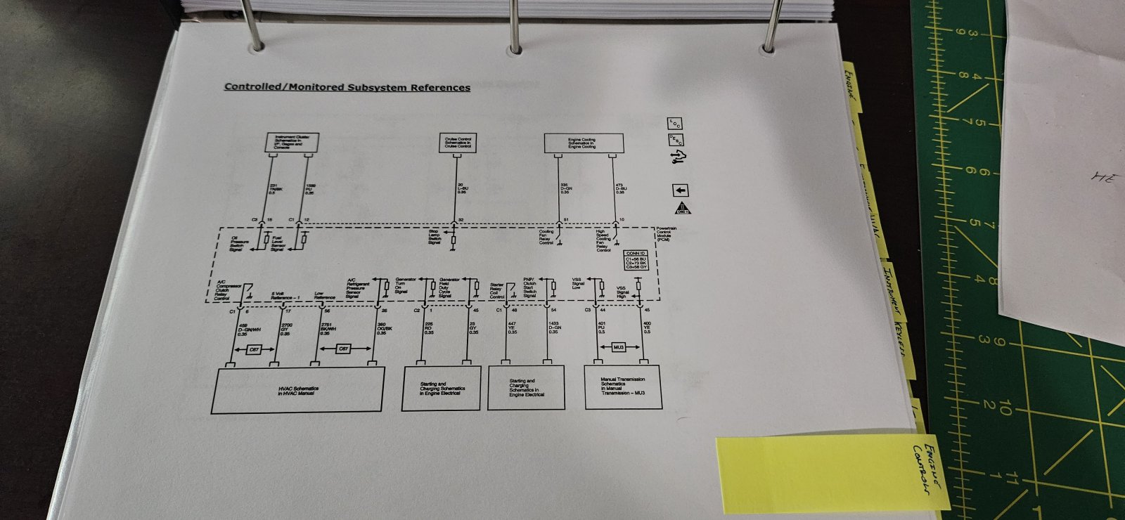
I also printed out all the Chilton Library drawings for my donor. They’ve been invaluable for answering figuring out differences and nuances so I don’t have to stop and ask questions on the forum.
Put both in a binder.
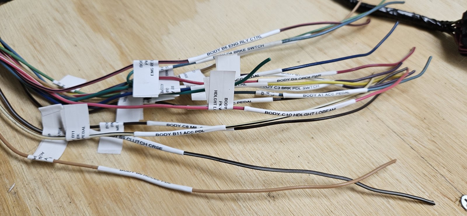
Some people here mentioned heat shrink labels and I love them. They only work on wires you’ve already cut, but they do not come off.
Finally, don’t put your wrist on a hot soldering iron.
Questions I’m working on right now:
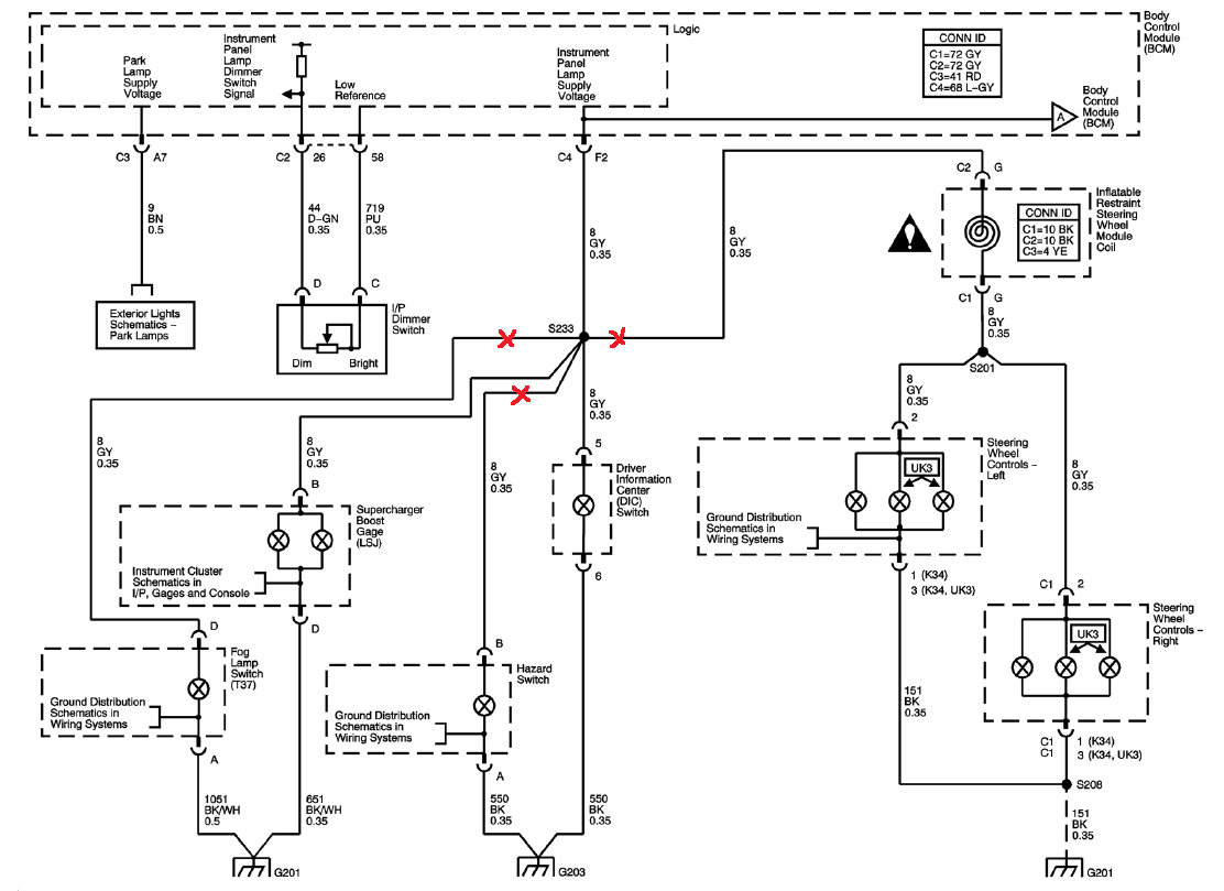
In part 8 we cut out a bunch of gray wires at a taped union. At the end I’m left with a taped union with three gray wires: to the boost gauge, to the BCM, and to the ‘Driver Information Center (DIC) Switch’. The video never mentions this connector at all, or the union again. Looks like it connects to the odometer cycling button on the dash. Is this connector kept?
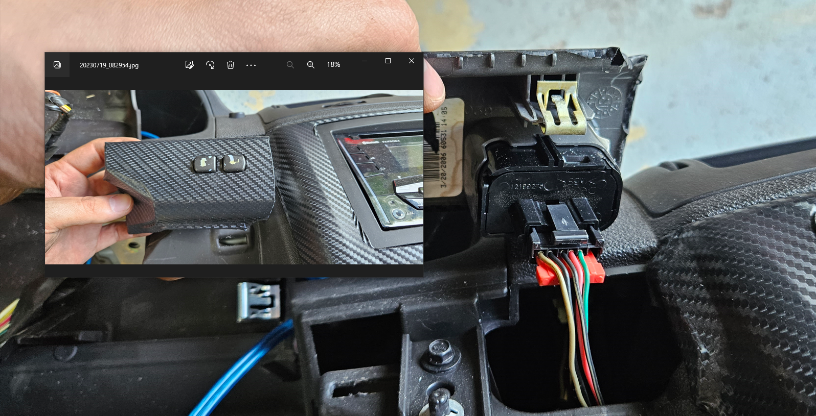
And lastly, in part 9, we cut out the clutch connector and brake connector. In part 10 it looks like they’re soldering back to their original wires? Or am I missing something? My harness is different as I have two brake connectors instead of one, and neither looks like the one in the video. I’m assuming that’s just a model/trim difference and I can leave them in the harness and tape them to the proper length.
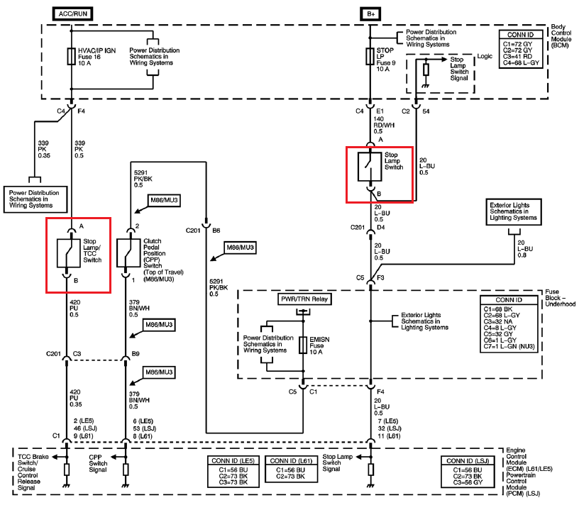
Part 5 step 17 – my daytime running lights had a light blue and dark blue wires, not purple. Not an issue, just a difference.
Part 5, step 20 – Difference ground layout meant I couldn’t match the harness shape. See post #30. May have to redo later.
Part 6, step 19 – typo on the video overlay, says light blue but should be light green.
Part 8 – I do not have passenger airbag light connector (step 7), traction control connector (step 12), or steering angle connector (step 22). Finding all the audio connectors was a crapshoot (see post #22).
Part 8 – I wanted to keep both the 12 volt outlets wired, but this one gets completely cut out when the C201 dash connector is removed. I’m keeping the plug to see if I can get power somewhere else.
Part 9, step 24 – I had to solder extensions to 3 wires in order to get the 7 inches for the dash cluster connector. I figure I’d rather be long than short and doing it now is easier than when it’s in the car.
Thing’s I’ve found helpful:
I printed out a transcript of the videos. Just the step title overlays, but it helps keep track of where I’m at and finding when looking ahead or back. It also is great for taking notes.
I also printed out all the Chilton Library drawings for my donor. They’ve been invaluable for answering figuring out differences and nuances so I don’t have to stop and ask questions on the forum.
Put both in a binder.
Some people here mentioned heat shrink labels and I love them. They only work on wires you’ve already cut, but they do not come off.
Finally, don’t put your wrist on a hot soldering iron.
Questions I’m working on right now:
In part 8 we cut out a bunch of gray wires at a taped union. At the end I’m left with a taped union with three gray wires: to the boost gauge, to the BCM, and to the ‘Driver Information Center (DIC) Switch’. The video never mentions this connector at all, or the union again. Looks like it connects to the odometer cycling button on the dash. Is this connector kept?
And lastly, in part 9, we cut out the clutch connector and brake connector. In part 10 it looks like they’re soldering back to their original wires? Or am I missing something? My harness is different as I have two brake connectors instead of one, and neither looks like the one in the video. I’m assuming that’s just a model/trim difference and I can leave them in the harness and tape them to the proper length.

Ross
Goblin Professor

- Ross Goblin Professor
You are making some serious progress!
I was able to keep the Cobalt buttons and accessory plugs. Button Panel wiring diagrams with cruise control.
To help identify the Cobalt connectors, here is my 2006 LSJ electrical harness videos here.
The top clutch switch is used for the cruise control, and if you are putting a DF hood on, you will have to cut down the height of the clutch pedal, and remount the cruise control switch in a lower location. (Or just skip that switch if you aren't using cruise control)
The Stop Lamp/TCC Switch on the left side of your diagram is only for the cruise control.
I was able to keep the Cobalt buttons and accessory plugs. Button Panel wiring diagrams with cruise control.
To help identify the Cobalt connectors, here is my 2006 LSJ electrical harness videos here.
The top clutch switch is used for the cruise control, and if you are putting a DF hood on, you will have to cut down the height of the clutch pedal, and remount the cruise control switch in a lower location. (Or just skip that switch if you aren't using cruise control)
The Stop Lamp/TCC Switch on the left side of your diagram is only for the cruise control.
Last edited:
Robinjo
Goblin Guru
- Robinjo Goblin Guru
I'll note that one of my plugs to the BCM (can't recall which one) was a bit short and I had to lengthen it after installing. Wasn't a huge deal in the end but would have been a whole lot easier on the table than hunched over in the cabin. It was one of the lock-tab connectors on the front, not the bolt in plug on the back.
Last edited:
Matt3458
Active Member
- Matt3458 Active Member
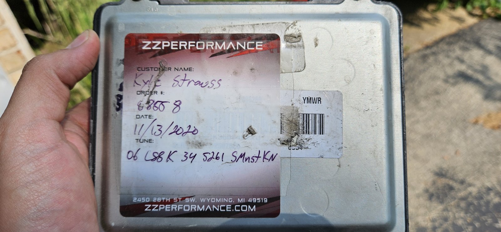
I looked up some details on the mystery tune the kid I bought it from mentioned. Curious how the goblin will run with in, or if I need to change it.
https://zzperformance.com/products/zzp-1-0-2-2-2-4-pcm
https://zzperformance.com/products/zzp-1-0-2-2-2-4-pcm
Desert Sasqwatch
Bigfoot Goblin
- Desert Sasqwatch Bigfoot Goblin
If all else fails, there are many SC tunes on the forum, just peruse @Ross build page - he has a library of tunes.
Robinjo
Goblin Guru
- Robinjo Goblin Guru
Also, I think you might be able to reach out to ZZP and have them supply the tune file for a small fee. Or just pull it from HP Tuners if you have it.
36 hours is what I logged. It was a happy day when I finished my harness. I then had months to worry about if I had done a decent job or not.
Wiring harness is complete. Took about 8 days with between a few to many hours depending on the day. Time to start prepping parts and get building.
36 hours is what I logged. It was a happy day when I finished my harness. I then had months to worry about if I had done a decent job or not.
Last edited:

Sluggonaut
Goblin Guru

- Sluggonaut Goblin Guru
36 hours is what I logged. It was a happy day when I finished my harness. I then had months to worry about if I had done a decent job or not.
This ^
It was great finishing the harness but then waiting for the kit and worrying about whether I did it right as I worked towards the first start was not so fun.

RCK605
Well-Known Member

- RCK605 Well-Known Member
This ^
It was great finishing the harness but then waiting for the kit and worrying about whether I did it right as I worked towards the first start was not so fun.
I just went through that this weekend. To my surprise it appears that I did everything correctly and engine fired of without issue. Well, no electrical issues anyway.
Similar threads

- Replies
- 0
- Views
- 65
- Replies
- 168
- Views
- 19K

- Replies
- 13
- Views
- 2K


- Replies
- 47
- Views
- 9K